– 39 –
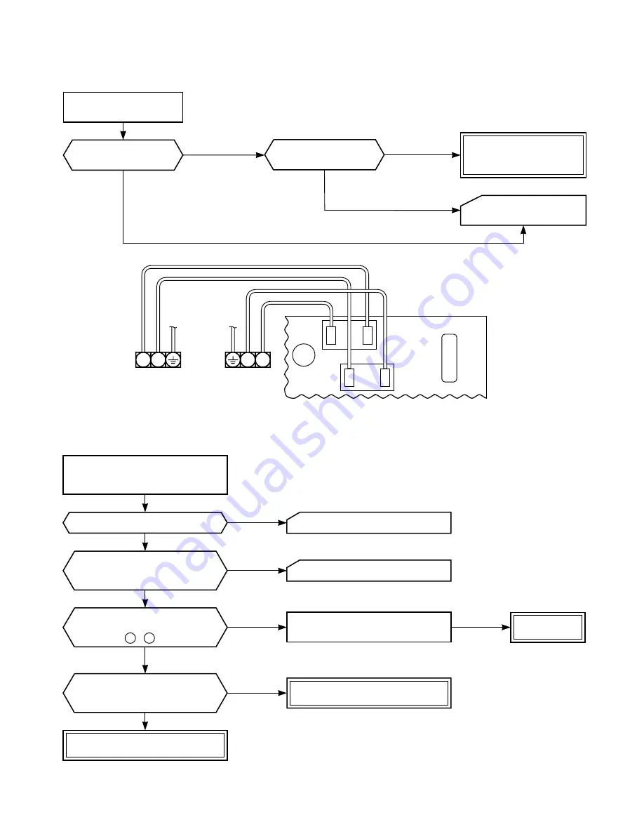
9-3-2. Power can not be Turned on after Replacing Indoor PC Board
<Checking Procedure>
9-3-3. Outdoor Unit does not Operate
RY01
C02
RY02
Brown
N
L
Power
terminal
block
T02
PC board
Blue
White
Black
1
2
Indoor
terminal
block
To the paragraph of
“No Power turns on”.
Does the OPERATION
lamp flash?
YES
NO
Connect the AC
Power supply
Return the wiring of the
power relay is returned to
the normal procedure.
Is it wired as shown
in Figure below?
YES
NO
Shut off the power supply
from AC outlet once and
turn it on after 5 seconds.
Does the OPERATION lamp flash?
Does the power turn on by
pushing the [START/STOP] button
of the remote control?
Is cable connection
between indoor and outdoor
units correct?
Check items as following procedure
in 9-3-4, 9-3-5, 9-3-6.
Replace the
PC board.
See "Power can not be turned on".
Relays (RY01, RY02)
or IC31 or IC30 is failure.
Correct cabling between
indoor and outdoor units.
NO
NO
NO
NO
YES
YES
YES
YES
See "Power can not be turned on".
Is AC220/230/240V
supplied between terminal block
1 - 2 ?
Summary of Contents for 10SAX-1
Page 46: ... 46 9 4 2 PC Board Layout BottomView Top View ...
Page 56: ......


