background image

TOSHIBA

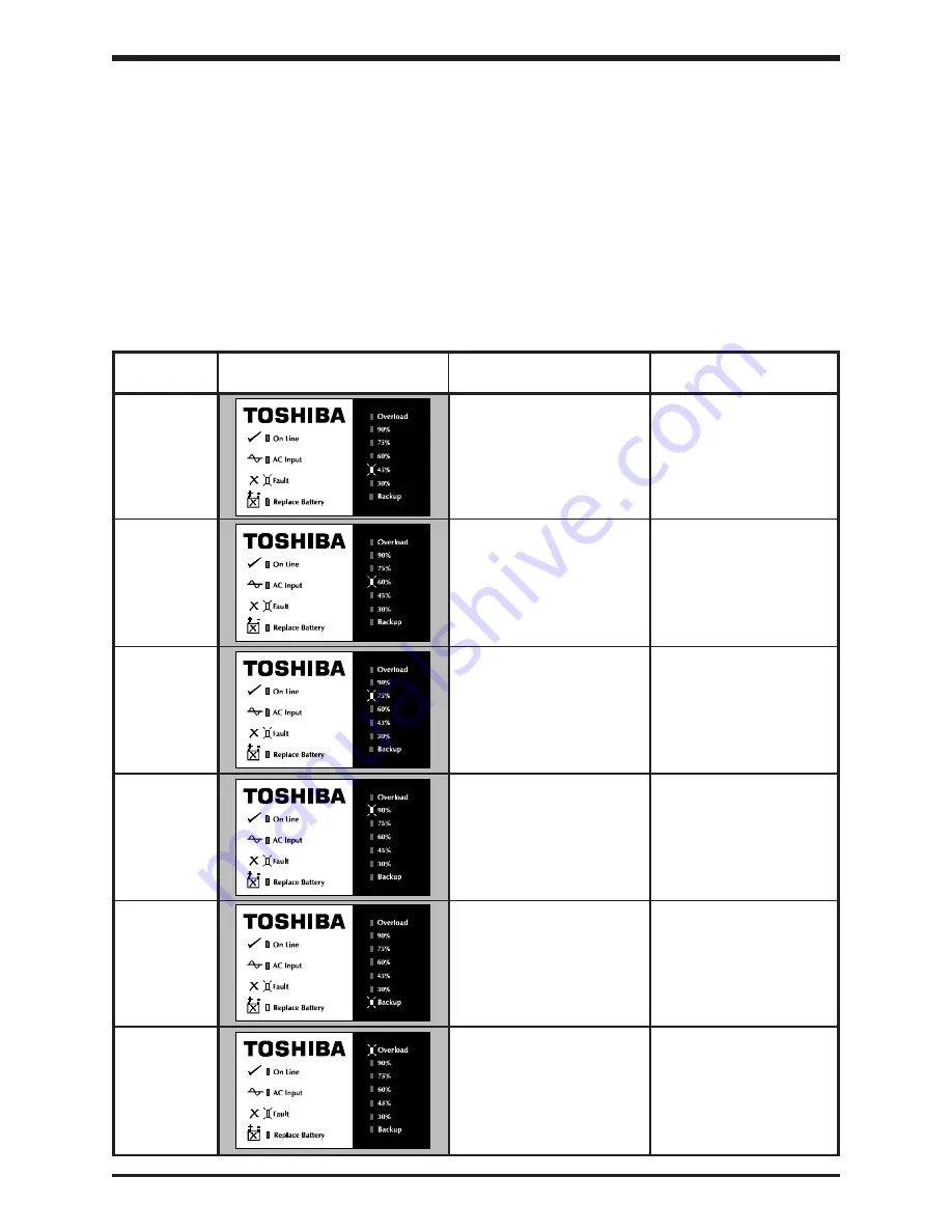
Fault

Display status

Probable cause

Corrective action

Remove cause of

Output low

Inverter fault or short

short circuit. If none is

voltage

circuit in UPS output

found, contact your

Toshiba service

representative.

Output

Resonance with load

Remove load

overvoltage

equipment

equipment one piece

at a time.

DC

Chopper fault

Contact your Toshiba

undervoltage

service representative.

Check for airflow

Cooling fin

Cooling fan outage or

restriction.  If none is

overheating

closed cooling airflow

found, contact your

path

Toshiba service

representative.

Battery damaged or

Battery

something wrong in the

Contact your Toshiba

problem

battery circuit (battery may service representative.

not be connected)

Output

Capacity of load

Review UPS rating

overload

equipment to high

or reduce load

equipment.

7.0

Troubleshooting Procedures

Faults are those abnormal conditions that can occur and cause the unit to shutdown normal

operation. The faults are detected by the protection circuitry (see System Protection Features

Section 5.2) in the unit. The UPS “Fault” lamp will light 

red

. "Troubleshooting" involves monitoring

the bar graph lamps on the front panel and then interpreting the readout by using the fault mode

display charts.

7.1

Non-Fatal Fault Mode

Non-fatal faults may or may not cause the unit to shut down.  These faults normally will

cause the UPS to transfer to bypass mode. Use "System Restart" procedures (see

Section 5.10) to transfer the UPS back to “On Line” mode.  Use the following chart to

decode the display.  All non-fatal faults will cause the red “Fault” LED to flash.

Non-Fatal Fault Mode Display Chart

7 - 1

Summary of Contents for 1500 Plus Series

Page 1: ...TOSHIBA UNINTERRUPTIBLE POWER SYSTEM SINGLE PHASE 6 8 1 0 1 2 kVA SINGLE PHASE 6 8 1 0 kVA PLUS March 2003 Part 46370 002 MANUFACTURED IN THE U S A OPERATION MANUAL 1500 and 1500 SERIES ...

Page 2: ...TOSHIBA ...

Page 3: ...t between the parties is the sole warranty of Toshiba International Corporation s UPS Division and any statements contained herein do not create new warranties or modify the existing warranty Any electrical or mechanical modifications to this equipment without prior written consent of Toshiba International Corporation will void all warranties and may void UL listing or other safety certification U...

Page 4: ...pection of the new UPS equipment 2 1 2 2 Storage of UPS equipment 2 1 2 3 Disposal 2 1 3 0 Precautions 3 1 3 1 Installation Precautions General 3 1 3 2 Prestart Precautions 3 2 3 3 Operating Precautions 3 2 4 0 Specifications 4 1 4 1 Standard Series Specifications 4 1 4 2 Plus Series Specifications with isolation transformer 4 3 5 0 Operating the UPS 5 1 5 1 Operation Modes 5 1 5 1 1 AC Input Mode...

Page 5: ... 6 5 9 Battery Check Function 5 6 5 10 System Reset 5 6 6 0 UPS Control Interface 6 1 6 1 DB25 Connector Pinout 6 1 6 2 RS 232C Communication Interface 6 2 6 2 1 UPS Shutdown via RS 232C 6 2 6 3 Dry Contact Interface 6 2 7 0 Troubleshooting Procedures 7 1 7 1 Non Fatal Fault Mode 7 1 7 2 Fatal Fault Mode 7 2 8 0 Preventive Maintenance Parts Replacement 8 1 8 1 Preventive Maintenance 8 1 8 2 Parts ...

Page 6: ...eference The manual is divided into major sections of interest Section 1 contains the product description with the theory of operation and applications All of the initial inspection storage installation operating and prestart precautions can be found in Sections 2 and 3 Section 4 contains the equipment standard specifications Section 5 outlines the operating modes protective features battery recha...

Page 7: ...d may result in injury Equipment damage may also occur 4 Attention warnings The attention warning symbol is an exclamation mark enclosed in a triangle which precedes the 3 16 high letters spelling the word ATTENTION The Attention warning symbol is used to indicate situations and conditions that can cause operator injury and or equipment damage Other warning symbols may appear along with the Danger...

Page 8: ... VA Plus Yuasa NP4 12FR 5 800 VA 800 VA Plus 1000 VA 1000 VA Plus Yuasa HPH5 12FR 5 1200 VA Misuse of this equipment could result in human injury and equipment damage In no event will Toshiba Corporation be responsible or liable for either indirect or consequential damage or injury that may result from the use of this equipment Do not dispose of the batteries in a fire The batteries may explode Do...

Page 9: ... battery is inadvertently grounded If inadvertently grounded remove source of ground Contact with any part of a grounded battery can result in electrical shock The likelihood of such shock will be reduced if such grounds are removed during installation and maintenance 7 Verify circuit polarities prior to making connections 8 Disconnect charging source and load prior to connecting or disconnecting ...

Page 10: ...NCERNANT LA SÉCURITÉ Cette notice contient des instructions importantes concernant la sécurité Une battery peut présenter un risque de choc électrique de brûlure par transfert d énergie Pour le remplacement utiliser le même nombre de batteries du modéle suivant CONSERVER CES INSTRUCTIONS ATTENTION ATTENTION L élimination des batteries est règlementèe Consulter les codes locaux à cet effet ATTENTIO...

Page 11: ...terruption 1 2 Application and Use Toshiba s 1500 and 1500 Plus Series of on line uninterruptible power supply UPS systems provide continuous computer grade ac power in a compact high performance and energy efficient unit The UPS unit assures safe and reliable operation of critical office equipment This can range from word processors and personal computers to mini computers and local area networks...

Page 12: ...efore storing 1 Charge the units batteries 2 Place the STOP RUN switch in the STOP position Storing 1 Store within a temperature range of 20 to 40 C 4 to 104 F 2 For best results store the UPS in the original shipping container and place on a wood or metal pallet 3 The optimum storage temperature is 21 C 70 F Higher ambient temperatures cause UPS batteries to need recharging more frequently After ...

Page 13: ...ubject to contamination such as high levels of airborne dust metal particles or inflammable gas 7 Avoid installation near sources of electrical noise and always make sure that the unit ground is intact to prevent electrical shock and to help reduce electrical noise 8 Do not install where water or any foreign object may get inside the UPS 9 This UPS generates and can radiate radio frequency energy ...

Page 14: ... with a load whose rated input is greater than the rated UPS output 4 Do not use the UPS to provide power to motors that require high starting current or a long starting time such as vacuum cleaners and machine tools oversizing for lock rotor current required 5 Do not insert metal objects or combustible materials in the unit s ventilation slots 6 Do not place hang or paste any objects on the top o...

Page 15: ...ctor 3 0 Environment Operating temperature 32 to 104 F 0 to 40 C optimal at 77 F 25 C Storage temperature 4 to 104 F 20 to 40 C Operatinghumidity 30 to 90 no condensation Altitude Less than 3000 ft 1000 m above sea level External dimensions 8 00W x 20 38D x 10 00H in 203W x 518D x 254H mm Net weight 40 3 lb 18 3 kg 40 3 lb 18 3 kg 43 7 lb 19 8 kg Acoustical noise 50 dB at max output measured 3 3 f...

Page 16: ...timal at 77 F 25 C Storage temperature 4 to 104 F 20 to 40 C Operatinghumidity 30 to 90 no condensation Altitude Less than 3000 ft 1000 m above sea level External dimensions 8 00W x 20 38D x 10 00H in 203W x 518D x 254H mm Net weight 43 7 lb 19 8 kg Acoustical noise 50 dB at max output measured 3 3 ft 1 m from front panel Efficiency ac dc ac 87 Switches Bypass switch Automatic bypass is provided w...

Page 17: ... 3 0 Environment Operating temperature 32 to 104 F 0 to 40 C optimal at 77 F 25 C Storage temperature 4 to 104 F 20 to 40 C Operatinghumidity 30 to 90 no condensation Altitude Less than 3000 ft 1000 m above sea level External dimensions 8 00W x 20 38D x 10 00H in 203W x 518D x 254H mm Net weight 57 5 lb 26 1 kg 57 5 lb 26 1 kg 60 9 lb 27 6 kg Acoustical noise 50 dB at max output measured 3 3 ft 1 ...

Page 18: ...ion shows circuit power flow in battery backup mode When commercial ac power failures occur the UPS s batteries instantly begin supplying dc voltage to the UPS s main inverter circuit This circuit changes inverts the dc power into ac power The ac power is available at the unit s output receptacles This back up process will continue until the UPS s battery voltage drops below a specific minimum lev...

Page 19: ...erter circuit after first correcting the fault Toggle the STOP RUN switch on the unit s front panel first to STOP and then back to RUN This procedure resets the UPS and transfers back to inverter During circuit bypass mode the AC Input LED is ON the On Line LED is OFF and the Fault LED may be ON or OFF See Section 9 2 Panel Layout 5 2 System Protection Features UPS batteries Bypass circuit UPS mai...

Page 20: ...cator Function Chart Alarms for the battery backup mode or low battery voltage will stop automatically when AC input voltage is restored Alarms for a fault condition will continue to sound until the UPS has been reset see Section 5 10 System Reset 5 3 3 Visual and Audible Indicator Function Chart 5 3 Overcurrent OC Problem in chopper or 1 Fault LED 1 Auto inverter circuit is ON transfer 2 On Line ...

Page 21: ...supplied to the UPS Unit FAULT red lamp Lights red when the UPS unit has tripped in the fault mode REPLACE BATTERY red lamp Lights red to indicate batteries may need to be replaced 5 5 UPS On Line Mode Display The following chart shows normal operating conditions when the UPS On Line lamp is green Flashing LED Steady lit LED Output Display Status Explanation When output current is between 30 and 1...

Page 22: ...rged Discharge shut off point Charging current 0 4 amp A 0 0 The recharge process usually consists of three periods During the first period the current is maintained at approximately 0 4 amperes In the second period the constant voltage control starts and the current gradually decreases as the batteries continue to charge In the third period a slight current flows into the batteries to keep them f...

Page 23: ...l begin operation in the bypass mode An automatic voltage level test of the batteries is made while operating in the bypass mode for five seconds A failure of this first test will activate visual and audible alarms see section 5 3 3 battery problem If this test is passed then the UPS will auto transfer from bypass mode to on line operating mode A ten second automatic voltage check of the batteries...

Page 24: ...ents for the DB25 connector Pin Symbol Description 1 0V Supply used by Slide In Options cards 2 9V Supply used by Slide In Options cards 3 RXD_UPS UPS receive line 4 TXD_UPS UPS transmit line 5 TXD_AUX Auxiliary transmit line 6 RXD_AUX Auxiliary receive line 7 not used 8 SNMPSIG1 SNMP option card function 9 RS_Common Common line for RS 232C communication 10 SNMPSIG2 SNMP option card function 11 DT...

Page 25: ...ernal batteries a shutdown order can be sent to the UPS telling it to turn OFF after a user specified amount of time This function can allow you to stop discharging the UPS batteries after an orderly system shutdown has been completed The UPS can be programmed to turn OFF up to 8 minutes after the shutdown command is given This command can be cancelled before the specified time has elapsed 6 3 Dry...

Page 26: ...utput Capacity of load Review UPS rating overload equipment to high or reduce load equipment 7 0 Troubleshooting Procedures Faults are those abnormal conditions that can occur and cause the unit to shutdown normal operation The faults are detected by the protection circuitry see System Protection Features Section 5 2 in the unit The UPS Fault lamp will light red Troubleshooting involves monitoring...

Page 27: ...stem Trouble with the control error PWB 7 2 7 0 Troubleshooting Procedures 7 2 Fatal Fault Mode Fatal faults may or may not cause the UPS to shutdown Use System Reset procedures see Section 5 10 to transfer UPS back to On Line mode Use the following chart to decode the display All fatal faults will cause the red Fault LED to light continuously Fatal Fault Mode Display Chart Flashing LED Steady lit...

Page 28: ...lacement of certain UPS parts 1 Batteries VRLA batteries are maintenance free with respect to electrolyte only The charging voltage temperature performance and connection resistance must be monitored periodically Necessary corrective actions must be made in order to assure safe reliable power is supplied by the UPS The aforementioned items affect the life of batteries so replacement should be done...

Page 29: ... VA 15 0A LittleFuse 314015 1200 VA 15 0A LittleFuse 314015 600 VA Plus 15 0A LittleFuse 314015 800 VA Plus 15 0A LittleFuse 314015 1000 VA Plus 15 0A LittleFuse 314015 8 0 Preventive and Scheduled Maintenance Parts Replacement 8 3 Fuse Rating Chart The following chart shows the recommended fuses for all UPS sizes 8 2 ...

Page 30: ...nnector Fuse Computer Interface Connector Output Receptacles Air Vents 20 38 9 0 External Dimensions Shipping Weights Panel Layout 9 1 External Dimensions Front View Rear View Side View Run Stop switch 0 Stop 1 Run 9 1 Slide in Option Card ...

Page 31: ...Weights Panel Layout 9 2 Panel Layout 9 3 Shipping Weights UPS Shipping Weight Model Pounds Kilograms 600 VA 48 8 22 2 800 VA 48 8 22 2 1000 VA 52 2 23 7 1200 VA 52 2 23 7 600 VA Plus 66 0 30 0 800 VA Plus 66 0 30 0 1000 VA Plus 69 4 31 5 9 2 ...

Page 32: ...TOSHIBA TOSHIBA INTERNATIONAL CORPORATION INDUSTRIAL DIVISION 13131 West Little York Rd Houston Texas 77041 Tel 800 231 1412 Fax 713 466 8773 Telex 762078 Printed in U S A ...

Reviews: