background image

ABC

D

E

F

G

H

ABC

D

E

F

G

H

2

1

3

4

5

6

7

8

2

1

3

4

5

6

7

8

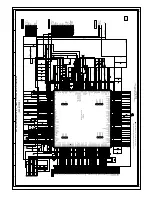
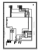
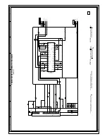
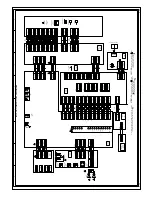
X101

100GT01615

16MHz

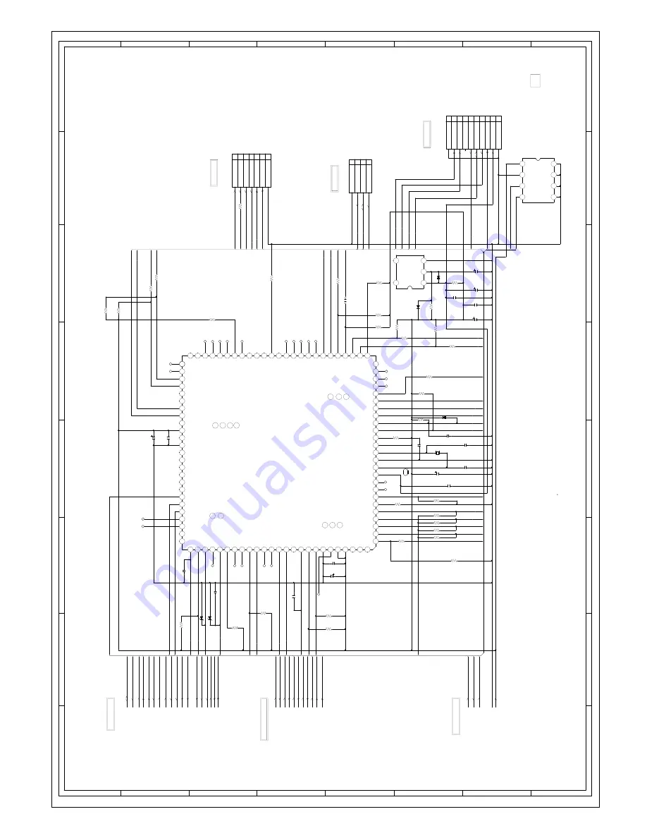
IC101

OEC7148A

MICON IC

11

0

100

11

12

13

14

15

16

17

18

19

2

20

21

22

23

24

25

26

27

28

29

3

30

31

32

33

34

35

36

37

38

39

4

40

41

42

43

44

45

46

47

48

49

5

50

51

52

53

54

55

56

57

58

59

6

60

61

62

63

64

65

66

67

68

69

7

70

71

72

73

74

75

76

77

78

79

8

80

81

82

83

84

85

86

87

88

89

9

90

91

92

93

94

95

96

97

98

99

JG107

JG106

JG101

JG112

JG114

JG115

JG116

JG117

JG119

JG120

JG121

JG104

JG105

JG102

JG108

JG109

JG111

JG113

JG110

JG103

JG124

JG122

JG123

JG118

JG125

CP103

A2001WV2-7P

1

2

3

4

5

6

7

D103

UDZS5.6B

D102

UDZS5.6B

CP102

A2001WV2-10P

MICON_DATA

1

10

2

3

4

5

6

7

8

9

IC102

PST3229NR

RESET IC

123

4

5

D106

RB520S-30-TE61

D108

RB520S-30-TE61

D107

RB520S-30-TE61

CP101

A2001WV2-4P

1

2

3

4

C107

220

6.3V

YK

C114

220

6.3V

YK

C125

100

10V

YK

C128

0.47

50V

KA

C132

2.2

50V

KA

C119

220

6.3V

YK

W815

C115

18P

CH

C118

18P

CH

C113

0.1

B

C101

1B

C108

0.1

B

C105

0.1

B

C110

0.1

B

C117

0.1

B

C121

0.1

B

C126

0.01

B

C120

0.1

B

C127

0.1

B

OF PRINTING AND SUBJECT TO CHANGE WITHOUT NOTICE

NOTE:

THIS SCHEMATIC DIAGRAM IS THE LATEST AT THE TIME

WAS RECEIVED IN GOOD CONDITION AND PICTURE IS NORMAL.

WITH THE DIGITAL TESTER WHEN THE COLOR BROADCAST

NOTE:THE DC VOLTAGE AT EACH PART WAS MEASURED

R146

100

R130

4.7K

R118

4.7K

R116

4.7K

R117

4.7K

R115

4.7K

R114

4.7K

R113

4.7K

R112

4.7K

R111

4.7K

R145

100

R139

100

R132

4.7K

R133

4.7K

R105

4.7K

R102

4.7K

R107

10K

R103

4.7K

R101

4.7K

R129

4.7K

R144

4.7K

R127

4.7K

R125

100

R121

10K

R124

100

R126

4.7K

R119

4.7K

R110

10K

R128

4.7K

R134

10K

R123

100

R142

4.7K

R143

10K

R106

10

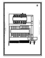
IC199

AT24C256N-10SU-2.7

EEP ROM IC 256K IC

1

2

3

4

5678

AGC

SDA1

AUDIO_MUTE

SCL1

EXT_MUTE-H

AFT

AGC

SCART1_Y

EEPROM_SCL

SCALER_RESET

EEPROM_SDA

DVS

POWER_FAIL

SCART1_Y

POWER_ON-H

DVS

LCD-H

LCDON

STAND-BY

SCALER-H

AUDIO_MUTE

START_SW

EXT_MUTE-H

DVD_RESET

4SI_SCL

4SI_SDA_IN

4SI_SDA_OUT

4SI_CHIP_SE

SCALER_RESET

AT+3.3V

SCALER_RESET

4SI_CHIP_SE

IIC_OFF

4SI_SCL

LCD-H

4SI_SDA_IN

4SI_SDA_OUT

C_SYNC

LCDON

DVD_POWER

DVD_RX&RX

STAND-BY

DVD_TX&TX

START_SW

DVD_RESET

AFT

REMOCON_IN

STANDBY_LED

KEY-B

KEY-B

KEY-A

KEY-A

SYNC_HD

RTS0

CLK0

DVD_RX&RX

DVD_TX&TX

EEPROM_SCL

EEPROM_SDA

IIC_OFF

DVD_TX&TX

DVD_RX&RX

RTS0

CLK0

P.CON+3.3V

P.CON+3.3V

AT+5V

4SI_CHIP_SE

4SI_SDA_OUT

STANDBY_LED

4SI_SDA_IN

REMOCON_IN

POWER_FAIL

POWER_ON-H

SCALER-H

DVD_POWER

4SI_SCL

SYNC_HD

C_SYNC

CNVSS

SCL1

SDA1

AT+5V

CNVSS

GND

AT+3.3V

EEPROM_SCL

EEPROM_SDA

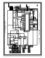
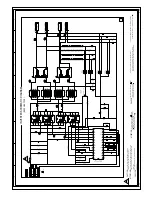
(SCALER PCB)

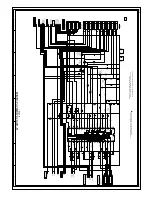
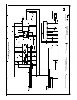
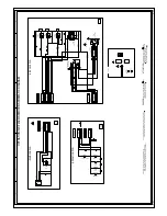
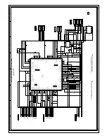
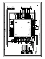
MICON SCHEMATIC DIAGRAM

H-26

H-25

NC

NC

NC

NC

NC

NC

NC

NC

NC

NC

NC

NC

NC

NC

NC

NC

NC

NC

NC

NC

NC

NC

NC

ROM WRITER

GND

TX

BUSY

VCC

RX

CLK

CNVSS

RESET

NC

GND

NC

ROM WRITER

ROM WRITER

PC_CONTROL

FROM/TO SYNC CEPA

FROM/TO REGULATOR

FROM/TO SCALER

VSS

A2

A1

A0

0000

GND

EEPROM_SCL

EEPROM_SDA

IIC_OFF

3.3

3.3

3.3

0

SDA

SCL

TEST

VCC

AVCC

VREF

4SI_CHIP_SE

4SI_SDA_IN

4SI_SDA_OUT

99

100

POWER FAIL

REMOCON IN

VCC

XIN

XOUT

VSS

BYTE

CNVSS

RESET

LED-H

NC

DVD POWER

LIGHT_CTL

4SI_SCL

CVBS/PC

VGA/YUV

HDMI/DVI

P50/^WRL/^WR

SD_SW1

SC2_CVBS_OUT-H

SC2_AUDIO_OUT-H

49

48

50

47

VCC

VSS

HEADPHONE_IN

EEPROM_SCL

EEPROM_SDA

STEREO_RESET

HP_MUTE

LCDON

NC

NC

START_SW

IIC_OFF

LCD_H

NC

AVSS

KEY-A

KEY-B

AFT

NC

NC

NC

POWER ON-H

DVD_RX & RX

26

27

NC

28

SCL1

SDA1

DVD_TX & TX

(CLK0)

(RTS0)

SDA2

SCL2

SYNC_HD

DVD_RESET

SCALER_RESET

(32KHz_OUT)

HDMI_RESET

(32KHz_IN)

NC

NC

NC

V_SYNC

NC

NC

C_SYNC

NC

NC

98

EPM

COMPONENT/HDMI

NC

D_TUNER_AFT_L

D_TUNER_SD_H

D_TUNER_AFT_H

SCART_AUDIO_SW

SCALER_RESET

S_DET

SCART3_SW

SW_SCART

LCDON

PDP_RLY

SCART3_SW

SCART2_SW

SCART1_SW

NC

AUDIO_MUTE

EXT_MUTE-H

NC

AGC

76

SCALER-H

75

HP_IN

NC

00

N

C

0

3.2

0

0

0

0

3.2

0

3.2

0

3.2

0

0

0

3.2

3.2

0

0

3.2

0

0

1.4

3.2

3.2

3.2

3.4

3.2

3.2

3.09

3.16

3.2

3.2

0000

3

.3

3

.3

3.2

3.2

3.2

3.2

0

0

00

00

3.2

3.2

3.2

3.2

0

0

0

0

0

0

0

0

0

3.2

3.2

0

0

0

0

0

0

0

0

0

0

3.2

3.2

0

0

0

3.4

3.2

3.2

3.2

0

0

2.75

2.75

0

0

0

0

0

2.51

0

0

0

0

0

0

PANEL_ON

RESET

CHIP_SELECT

4SI_SDA_IN

GND

4SI_SDA_OUT

4SI_SCL

AT+3.3V

OUT

NC

NC

GND

3.4

IN

3.4

0

16

3.2

PCBDS0

CEF174

Summary of Contents for 15DLV77C

Page 1: ...765GR The above model is classified as a green product 1 as indicated by the underlined serial number This Service Manual describes replacement parts for the green product When repairing this green product use the part s described in this manual and lead free solder 2 For 1 and 2 see the next page 2007 Toshiba Corporation ...

Page 2: ...ement of parts is not only confined to manufacture The same green parts used in manufacture must also be used as replacement parts 2 LEAD FREE SOLDER This product is manufactured using lead free solder as a part of a movement within the consumer products industry at large to be environmentally responsible Lead free solder must be used in the servicing and repair of this product WARNING This produc...

Page 3: ... your local authorities or the Electronic Industries Alliance www eiae org NOTE TO CATV INSTALLERS This is a reminder to call the CATV system installer s attention to Article 820 40 of the NEC which provides guidelines for proper grounding and in particular speci es that the cable ground shall be connected to grounding system of the building as close to the point of cable entry as practical For ad...

Page 4: ...during the following cases When you bring the unit directly from a cold place to a warm place When you use the unit in a room where you just turned on the heater or a place where the cold wind from the air conditioner directly hits the unit In summer when you use the unit in a hot and humid place just after you move the unit from an air conditioned room When you use the unit in a humid place Preca...

Page 5: ...function you can enjoy playback of interactive software with search function by using the menu displayed on the TV screen Menu Playback Some of the functions described in this owner s manual may not work with some discs Disc Mark Contents Disc Size Maximum playback time DVD video discs Audio Video moving pictures 12cm Approx 4 hours single sided disc Approx 8 hours double sided disc 8cm Approx 80 ...

Page 6: ...HF antenna has a 300 ohm twin lead wire use the 300 75 ohm matching transformer Connect the UHF 300 ohm twin lead wire to the combiner not supplied Connect the VHF 300 ohm twin lead wire to the 300 75 ohm matching transformer Attach the transformer to the combiner then attach the combiner to the antenna jack on the back of the TV DVD Connect the VHF 75 ohm cable and UHF 300 ohm twin lead wire to t...

Page 7: ...er Rear speaker Sub woofer Center speaker Signal ow Dolby Digital Dolby Digital is the surround sound technology used in theaters showing the latest movies and is now available to reproduce this realistic effect in the home You can enjoy motion picture and live concert DVD video discs encoded via the Dolby Digital recording system with this dynamic realistic sound by connecting the TV DVD to a 6 c...

Page 8: ...ory In addition to normal VHF and UHF channels this TV DVD can receive up to 113 Cable TV channels To use this TV DVD with an antenna set the TV CABLE selection to the TV position When shipped from the factory this selection is in the CABLE position 0 9 To ADD ERASE channels Press MENU then press or to select SETUP Press or to select the CH PROGRAM then press The TV will begin memorizing all the c...

Page 9: ...en for hearing impaired viewers You can also select the closed captions in SETUP menu in the TV mode Closed captions WHAT IS CLOSED CAPTIONING This television has the capability to decode and display closed captioned television programs Closed captioning will display text on the screen for hearing impaired viewers or it will translate and display text in another language Notes When selecting close...

Page 10: ...cting to do so may cause serious personal injury POWER Basic playback Press VOLUME or to adjust the volume 5 VOLUME 32 VOLUME PLAY STOP EJECT Reading J5X00401A Eng indb 29 3 5 2550 12 11 25 30 Basic playback To pause playback still mode Press PAUSE during playback To resume normal playback press PLAY The sound is muted during still mode To stop playback Press STOP To remove the disc Press EJECT Re...

Page 11: ... MODE in the stop mode 1 2 Press to return to the left column then press to select the Program Playback and press ENTER The programs you selected will start to playback in order To resume normal playback select Mode Off in step 2 Notes In playing back the Video CD with PBC you cannot set Program playback The program is canceled when you eject the disc or turn the power off Q To change the program ...

Page 12: ... recorded by Joliet Recording Speci cation can be played back the le name is displayed within 15 letters on the screen Long le names will be condensed The music les recorded by Hierarchical File System HFS cannot be played Limitations on display The maximum number for display is 15 letters Available letters for display are the following capital or small alphabets of A through Z numbers of 0 throug...

Page 13: ...to play this video will appear on the screen When you attempt to play DivX VOD the number of plays is limited and the right message will appear on the screen If you wish to play it select Yes If the number of plays goes over the limit then Rental Expired will be displayed In this case the le will not be played View DivX VOD Rental This rental has 5 views left Do you want to use one of your 5 views...

Page 14: ...ority language of each disc Off Subtitle Subtitles do not appear Notes If the selected language is not recorded on the disc the rst priority language is selected If you want to change the OSD language you can perform it by TV SETUP MENU 21 TV Screen You have the following screen sizes to choose from 4 3 Letter box Select this mode when connecting to a conventional TV When playing back a wide scree...

Page 15: ...which you submit to your provider Press or to select DivX R VOD Then press ENTER Your 8 character registration code is displayed Make a note of the code as you will need it when you register with a DivX VOD provider Then press ENTER to select Done J5X00401A Eng indb 49 3 5 2550 12 11 46 50 Function setup ENTER RETURN 0 9 Temporary cancel the rating level by DVD disc Depending on the DVD disc the d...

Page 16: ... subtitles Subtitles are cleared Press the SUBTITLE button 36 Angle cannot be changed Multi angles are not recorded on the DVD disc 35 appears on the screen The function is prohibited with the unit or the disc 31 REMOTE CONTROL The remote control does not function Aim the remote control at the remote sensor Operate within approx 5 meters or reduce the light in the room Clear the path of the beam T...

Page 17: ...PLIED WARRANTIES CONDITIONS AND REPRESENTATIONS THEN SUCH IMPLIED WARRANTIES CONDITIONS AND REPRESENTATIONS ARE OTHERWISE LIMITED IN DURATION TO THE TERM OF THIS EXPRESS WRITTEN LIMITED WARRANTY TO THE EXTENT NOT PRECLUDED BY LAW STATUTORY OR OTHERWISE THIS WRITTEN WARRANTY SUPERCEDES AND SPECIFICALLY DISCLAIMS ANY OTHER WARRANTY CONDITION OR REPRESENTATION NOT STATED IN THIS WARRANTY WHETHER MADE...

Page 18: ...quired Marking The rating sheet and the safety caution are on the rear of the unit CERTIFICATION COMPLIES WITH FDA RADIATION PERFORMANCE STANDARDS 21 CFR SUBCHAPTER J PREPARATION OF SERVICING The laser diode used for a pickup head may be destroyed with external static electricity Moreover even if it is operating normally after repair when static electricity discharge is received at the time of rep...

Page 19: ...ation transformer for this check Use a leakage current tester Fig 1 or a metering system which complies with Underwriters Laboratories UL 1492P Measure for current from all exposed metal parts of the cabinet to a known earth ground particularly any exposed metal part having a return path to the chassis Any current measured must not exceed 0 5mA Any measurement not within the limits outlined above ...

Page 20: ...al power company For units intended to operate from battery power or other sources refer to the operating instructions GROUNDING OR POLARIZATION This unit is equipped with a polarized alternating current line plug a plug having one blade wider than the other This plug will fit into the power outlet only one way This is a safety feature If you are unable to insert the plug fully into the outlet try...

Page 21: ... equipment turn off the power and unplug all of the equipment from the wall outlet Failure to do so may cause an electric shock and serious personal injury Read the owner s manual of the other equipment carefully and follow the instructions when making any connections SOUND VOLUME Reduce the volume to the minimum level before you turn on the product Otherwise sudden high volume sound may cause hea...

Page 22: ...ICAL CODE ANTENNA DISCHARGE UNIT NEC SECTION 810 20 ANTENNA LEAD IN WIRE GROUNDING CONDUCTORS NEC SECTION 810 21 GROUND CLAMPS POWER SERVICE GROUNDING ELECTRODE SYSTEM NEC ART 250 PART H GROUND CLAMP ELECTRIC SERVICE EQUIPMENT NEC NATIONAL ELECTRICAL CODE S2898A ...

Page 23: ...e soldering on the short circuit position after the connection of Pick Up PCB and DVD MT PCB connector NOTE Fig 1 Before your operation please read PREPARATION OF SERVICING Use the Lead Free solder Manual soldering conditions Soldering temperature 320 20 C Soldering time Within 3 seconds Soldering combination Sn 3 0Ag 0 5Cu When Soldering Removing of solder use the draw in equipment over the Pick ...

Page 24: ...e 7 key on the remote control unit Hold both keys for more than 2 seconds The On Screen Display message PASSWORD CLEAR will appear The 4 digit password has now been cleared 1 2 3 4 5 6 7 8 PARENTAL CONTROL RATING LEVEL 4 DIGIT PASSWORD CANCELLATION The disk cannot be taken out by setting the Tray Lock please follow the steps below Turn Unit ON Set the DVD to the Stop Mode Press it in order of SETU...

Page 25: ...LE OF CONTENTS GENERAL SPECIFICATIONS DISASSEMBLY INSTRUCTIONS 1 REMOVAL OF MECHANICAL PARTS AND P C BOARDS 2 REMOVAL OF DVD DECK PARTS 3 REMOVAL AND INSTALLATION OF FLAT PACKAGE IC SERVICE MODE LIST SERVICING FIXTURES AND TOOLS RE WRITE FOR DVD FIRMWARE CONFIRMATION OF CHECK SUM WHEN REPLACING EEPROM MEMORY IC ELECTRICAL ADJUSTMENTS TROUBLESHOOTING GUIDE BLOCK DIAGRAMS DVD AV POWER SCALER PRINTED...

Page 26: ...Tuner and System 1Tuner Receive CH Destination US W CABLE CH Coverage 2 69 4A A 5 A 1 A I J W W 1 W 84 Intermediate Picture FP 45 75MHz Frequency Sound FS 41 25MHz FP FS 4 50MHz Preset CH No Stereo Dual TV Sound US Stereo Tuner Sound Muting Yes G 4 Signal Video Signal Input Level 1 V p p 75 ohm Output Level S N Ratio Weighted Horizontal Resolution at DVD Mode RGB Signal Output Level Audio Signal I...

Page 27: ... Dark Remocon Yes Remocon Format ORION Format NEC Custom Code 71 8E h Power Source Voltage D C 3V UM size x pcs UM 4 x 2 pcs Total Keys 47 Key Keys Power Yes 1 Yes 2 Yes 3 Yes 4 Yes 5 Yes 6 Yes 7 Yes 8 Yes 9 Yes 0 Yes Play Yes Stop Yes Search Yes Search Yes Skip Yes Skip Yes Slow Yes Slow Yes Pause Still Step Yes Recall Yes TV DVD Yes Cancel Yes Audio Select Yes Angle Yes Subtitle Yes Top Menu Yes...

Page 28: ...s BBE No SRS WOW SRS 3D Focus Tru Bass No Valiable Audio Out No Tuning CH Program Yes TV Cable Yes ADD DELETE Yes Label CH Label No Video Label No Favorite CH No V Chip No Type RRT Setup No Lock Hotel Lock No Channel Lock No Video Lock No Panel Lock No OSD Language Closed Caption Yes CC Advanced No Picture Size No Picture Scroll No Cinema Mode No Aspect No Backlight No PFC Power Factor circuit No ...

Page 29: ... Screen Saver No Audio DAC 192kHz 24bit G 12 Accessories Owner s Manual Language English French w Guarantee Card Yes Remote Control Unit Yes Rod Antenna No Poles Terminal Loop Antenna No Terminal U V Mixer No DC Car Cord Center No Guarantee Card No Warning Sheet No Circuit Diagram No Antenna Change Plug No Service Facility List No Important Safeguard No Dew AHC Caution Sheet No Quick Set up Sheet ...

Page 30: ...s Other Terminal Headphone G 14 Set Size Approx W x D x H mm 476 x 230 x 353 5 w o Handle Stand Approx W x D x H mm 476 x 78 5 x 312 5 G 15 Weight Net Approx 6 0kg 13 2 lbs Net w o Handle Stand Approx 4 5kg 9 9 lbs Gross Approx 8 0kg 17 6 lbs G 16 Carton Master Carton No Content Sets Material Dimensions W x D x H mm Description of Origin Gift Box Material Single White W Color Photo Label No Dimens...

Page 31: ...ONS G 19 AC Power Adapter Provided Accessories Power Requirement AC 120V 60Hz Max Power Consumption Adapter Only at AC 65 W DC Output DC Jack DC12V 4 5A Dimension Approx W x D x H mm 150 x 72 x 43 Weight Approx 450g A3 6 ...

Page 32: ...Ass y in the direction of arrow C Fig 1 1 1 1 Stand A B 3 2 3 2 C Hinge Ass y Stand Angle 1 1 1 1 1 1 2 1 1 1 1 3 2 Fig 1 3 1 Angle Back 1 1 1 4 DVD DECK Refer to Fig 1 4 1 2 3 4 5 6 7 8 Short circuit the position shown in Fig 1 4 using a soldering iron If you remove the DVD Deck with no soldering the Laser may be damaged Disconnect the following connectors CP2301 CP2302 and CP2303 Remove the 4 sc...

Page 33: ...ARATION OF SERVICING Use the Lead Free solder Manual soldering conditions Soldering temperature 320 20 C Soldering time Within 3 seconds Soldering combination Sn 3 0Ag 0 5Cu When Soldering Removing of solder use the drawing equipment over the Pick Up Unit to keep the Flux smoke away from it When installing the DVD Deck remove all the soldering on the short circuit position after the connection of ...

Page 34: ... Jack PCB in the direction of arrow A Remove the Shield Jack Side and Plate Jack Side in the direction of arrow B OPERATION PCB REMOCON PCB Refer to Fig 1 10 Fig 1 10 2 Remocon PCB Operation PCB Operation 2 PCB 1 1 A 2 B Holder PCB DVD Holder PCB TV 3 3 C D 4 4 CP2251 E 5 5 1 9 AV PCB Refer to Fig 1 9 1 2 3 4 5 6 7 8 9 Remove the 2 screws 1 Remove the screw 2 Remove the screw 3 Remove the Plate Ja...

Page 35: ...1 Remove the 2 screws 2 Remove the Angle Hinge in the direction of arrow A Remove the 8 screws 3 Remove the LCD Cover in the direction of arrow B Remove the 4 screws 4 Remove the LCD Panel in the direction of arrow C Front Cabinet 1 Angle Hinge 1 2 A 3 4 4 4 4 B C LCD Panel Fig 1 11 2 3 3 3 3 3 3 LCD Cover 3 ...

Page 36: ...g 2 1 C 2 2 Remove the Insulator F Remove the Insulator R Unlock the support 1 Remove the Gear Middle Remove the screw 2 Remove the Rack Feed Ass y Remove the screw 3 Remove the Switch PCB Ass y Remove the screw 4 Remove the Gear Feed Remove the 2 screws 5 Remove the Feed Motor Remove the Gear Motor 1 2 3 4 5 6 7 8 9 10 11 12 13 SWITCH PCB ASS Y GEAR MIDDLE GEAR FEED RACK FEED ASS Y FEED MOTOR Ref...

Page 37: ... for pressing of the insert Feed Motor Gear Motor Pick Up Side Printing Surface Fold it by 90 20 1mm Fold it by 90 30 1mm NOTE 1 2 3 4 When installing the Rack Feed Ass y push both ends to align the teeth as shown Fig 2 2 B Then install it In case of the Gear Motor installation check if the value of the Fig 2 2 C is correct When installing the wire of the Switch PCB Ass y install it correctly as F...

Page 38: ...ring the IC leads completely Fig 3 2 Blower type IC desoldering machine IC 3 When IC starts moving back and forth easily after desoldering completely pickup the corner of the IC using a tweezers and remove the IC by moving with the IC desoldering machine Refer to Fig 3 3 NOTE Some ICs on the PCB are affixed with glue so be careful not to break or damage the foil of each IC leads or solder lands un...

Page 39: ...eld Wire Refer to Fig 3 7 NOTE Do not absorb the solder to excess Fig 3 7 Soldering Iron IC Braided Shield Wire 4 When bridge soldering between terminals and or the soldering amount are not enough resolder using a Thin tip Soldering Iron Refer to Fig 3 8 Fig 3 8 Thin tip Soldering Iron IC 5 Finally confirm the soldering status on four sides of the IC using a magnifying glass Confirm that no abnorm...

Page 40: ...rs are displayed on the screen Can be checked of the INITIAL DATA of MEMORY IC Refer to the WHEN REPLACING EEPROM MEMORY IC STOP 7 2 sec VOL DOWN Minimum 6 2 sec VOL DOWN Minimum 9 2 sec DVD mode No disc TV mode ALL mode Display of the Adjustment MENU on the screen Refer to the ELECTRICAL ADJUSTMENT On Screen Display Adjustment Releasing of PARENTAL LOCK Refer to the PARENTAL CONTROL RATING LEVEL ...

Page 41: ...ate Logo screen will appear Unplug the AC cord then plug it in After the write set to the initializing of shipping Turn on the power and set the DVD mode Press both VOL DOWN button on the set and Channel button 4 on the remote control for more than 2 seconds The INITIALIZE 5 COMPLETE will appear on the screen Then unplug the AC cord and plug it in CHECK FOR THE FIRMWARE VERSION Turn on the power a...

Page 42: ...han 2 seconds ADDRESS and DATA should appear as FIG 2 1 2 3 4 INIT 3836 ROM 3B4E VOLUME 084E DVP 25C9 LCD ON 0000 OEC7148A 028 FIG 1 Initial setting data check sum POWER ON total hours 16 x 16 x 16 x thousands digit value 16 x 16 x hundreds digit value 16 x tens digit value ones digit value MICON Version Turn on the POWER and set to the TV mode Set the VOLUME to minimum Press both VOL DOWN button ...

Page 43: ...23 24 25 26 27 28 29 30 31 32 33 34 35 36 37 38 39 40 41 42 43 44 CAUTION Use an isolation transformer when performing any service on this chassis When removing a PCB or related component after unfastening or changing a wire be sure to put the wire back in its original position When you exchange IC and Transistor with a heat sink apply silicon grease on the contact section of the heat sink Before ...

Page 44: ...e adjustment mode display of Fig 1 1 press the channel button 26 on the remote control to select BRIGHT CENT Press the LEFT RIGTH button on the remote control until the white 2 7 is starting to be visible Receive the monoscope pattern VIDEO Input Press the INPUT SELECT button on the remote control to set to the AV mode Then perform the above adjustments 2 4 Playback the DVD 480i disc COMPONENT Inp...

Page 45: ...294 22 V POSI 73 73 71 87 73 74 23 BAK LIGHT CENT 70 70 70 70 70 70 24 BAK LIGHT MAX 255 255 255 255 255 255 25 BAK LIGHT MIN 00 00 00 00 00 00 26 BRIGHT CENT 134 134 134 134 123 134 27 BRIGHT MAX 170 170 170 180 170 170 28 BRIGHT MIN 60 60 60 60 60 60 29 TINT 131 128 135 140 128 128 33 CONTRAST CENTER N 70 70 70 70 70 70 34 CONTRAST MAX N 118 110 110 110 110 115 35 CONTRAST MIN N 50 50 50 50 50 5...

Page 46: ...01 CP2302 CP2303 CD2001 CD2301 CP2201 CP2202 CD7001 CP7003 CP7001 CP7002 CP7004 J4202 TU001 CP301 CP3803 CP3802 CP3804 CP4203 J4201 CD4202 CP2204 OPERATION 2 PCB OPERATION PCB SIDE JACK PCB REMOCON PCB SCALER PCB CP2251 AV PCB CP4204 SPEAKER J4401 J4402 CP4401 J4403 J4404 J4405 CP4403 CP4402 CP7201 CP801 CP204 CP202 CP203 CP3201 D 4 CD4204 CD2201 CD7201 ...

Page 47: ...AND PERIPHERAL CIRCUIT NO CHECK IC3809 AND PERIPHERAL CIRCUIT NO YES CHECK IC3806 AND PERIPHERAL CIRCUIT YES CHANGE AV PCB YES NO CONNECT CP3804 AND CP3201 IS CP3804 AND CP3201 CONNECTED IS THERE VOLTAGE AT PIN 2 OF IC3809 MORE THAN 3V IS THERE VOLTAGE AT PIN 3 PIN OF IC3806 3 3V IS THERE VOLTAGE AT PIN 7 OF Q3809 5V ...

Page 48: ...AND PERIPHERAL CIRCUIT YES NO CHANGE TU001 IS CP4403 AND CP4401 CONNECTED YES NO IS THERE SIGNAL AT PIN 14 OF TU001 CHANGE SP301 YES CHECK IC4201 AND PERIPHERAL CIRCUIT IS THERE SIGNAL AT PINS 3 AND 30 OF IC301 NO CHECK IC302 AND PERIPHERAL CIRCUIT YES IS THERE SIGNAL AT PINS 28 AND 30 OF IC4201 IS THERE SIGNAL AT PINS 2 AND 4 OF IC302 IS THERE SIGNAL AT PINS 1 AND 4 OF CP4403 ...

Page 49: ...CONNECT CD7201 NO YES IS CD7201 CONNECTED DOES BACK LIGHT SHINE YES NO CHANGE V2301 IS THERE SIGNAL AT IC7201 CHANGE IC7201 IS THERE SIGNAL AT PINS 5 6 8 9 11 12 14 15 17 AND 18 OF CD7201 NO YES CHECK IC801 CHECK THE CONNECTED OF CP3802 AND THE VOLTAGE PF PINS 1 3 ...

Page 50: ...IPHERAL CIRCUIT CONNECT CD4204 CHANGE IC4201 AND PERIPHERAL CIRCUIT NO NO YES CHANGE IC801 AND PERIPHERAL CIRCUIT CHECK C829 C835 C850 AND PERIPHERAL CIRCUIT IS CD4204 CONNECTED AND IS THERE SIGNAL AT PINS 1 3 AND 5 IS THERE SIGNAL AT C829 C835 AND C850 IS THERE SIGNAL AT PIN 31 OF IC4201 ...

Page 51: ...NOT APPEAR YES NO NO YES RECEIVE THE COLOR SIGNAL IS SETTING OF COLOR NORMAL CHANGE THE SETTING OF COLOR IS THE COLOR SIGNAL RECEIVED CHANGE SCALER PCB YES NO CHECK IC801 AND PERIPHERAL CIRCUIT IS THERE COLOR SIGNAL AT PINS 13 AND 31 OF IC801 ...

Page 52: ... DISPLAY DOES NOT APPEAR NO YES NO CHECK IC101 AND PERIPHERAL CIRCUIT CHECK NR801 AND PERIPHERAL CIRCUIT YES CHECK IC801 AND PERIPHERAL CIRCUIT IS THERE SIGNAL AT PINS 57 58 59 AND 60 OF IC801 IS THERE SIGNAL AT PINS 2 3 4 AND 5 OF IC101 ...

Page 53: ...D P CON 1 8V LINE YES NO YES NO DOES THIS HAVE SIGNAL AT PINS 151 AND 153 OF IC4001 DOES NOT DISPLAY DVD PICTURE CHECK THE DISC CHECK PINS 9 AND 7 OF CD703 AND PERIPHERAL CIRCUIT CHANGE IC4001 DOES THIS DISPLAY LOGO PICTURE DOES IC4001 GETS P CON 3 3V AND P CON 1 8V ...

Page 54: ...ND 206 OF IC4001 AND PERIPHERAL CIRCUIT CHANGE DVD DECK YES NO YES NO DOES THIS EJECT DISC AT CHANGE DVD DECK IS REMOTE KEY SET EFFECTIVELY DISC DOES NOT EJECT CHECK IC2301 AND PERIPHERAL CIRCUIT YES NO DOES THIS HAVE SIGNAL AT PINS 4 AND 5 OF CP2302 CHANGE IC2301 YES NO DOES THIS HAVE SIGNAL AT PINS 1 AND 2 OF CP2302 CHANGE IC4001 ...

Page 55: ...NO YES DOES THIS DISPLAY INCORRECT DISC CHANGE IC4001 DOSE NOT PLAY DVD DOES CD2001 CONNECT WITH CP2301 CORRECTLY NO IS THEVOLTAGE BETWEEN JG017 AND JG018 LESS THAN 0 6V DOES THIS DISPLAY READING MARK DOES DISC ROTATE CHANGE IC4001 NO CHANGE DVD DECK NO YES YES YES ...

Page 56: ... NO YES DOES THIS DISPLAY INCORRECT DISC CHANGE IC4001 DOES NOT PLAY CD DOES CD2001 CONNECT WITH CP2301 CORRECTLY NO IS THE VOLTAGE BETWEEN JG019 AND JG018 LESS THAN 0 6V DOES THIS DISPLAY READING MARK DOES DISC ROTATE CHANGE IC4001 NO CHANGE DVD DECK NO YES YES YES ...

Page 57: ... SIGNAL AT PINS 113 115 116 AND 118 OF IC4001 NO SOUND DVD CD ANALOG AUDIO REFER TO LCD SECTION CHECK PINS 7 AND 8 OF IC8502 AND PERIPHERAL CIRCUIT CHANGE IC8502 CHANGE IC4001 NO YES YES NO DOES THIS HAVE SIGNAL AT PIN 1 OF CD703 DOES THIS HAVE SIGNAL AT PIN 110 OF IC4001 NO SOUND DVD CD DIGITAL AUDIO CHECK IC4001 AND PERIPHERAL CIRCUIT CHECK J4202 AND PERIPHERAL CIRCUIT ...

Page 58: ...L SPINDLE SLED FOCUS TRACK_PWM TRAY_CLOSE OPEN DRVSB DVD BLOCK DIAGRAM HA0 A19 HD0 D15 MEMCS0 RD WR SD_A0 A11 SD_D0 D15 64M SDRAM IC4005 EM638165TS 7G ML MC MD AMCLK ABCLK ALRCLK ASDATA0 F 1 SPDL_SEN F 2 RAMDQM CLK WE CS1 CAS RAS CS0 SD_BA0 RX RDY 5 DVD_RESET 4 3 2 TX SSCCLK START_SW CD702 SPDIF 134 2 3 5 ZERO DVD_A_OUT_L DVD_A_OUT_R 7 9 1 V Y_VIDEO CD703 U C_VIDEO DEC_VIDEO_C DEC_VIDEO_B DVD_POWE...

Page 59: ...S_IN AUDIO R SCALER SWITCH_CVBS SW_VIDEO_C SP301 S0407N03 A 1 5W 1 5W HEAD PHONE JACK J4401 MSJ 2000_AG J4402 MDC 012V1 A_LR SCL1 SDA1 AFT DVD J4405 AV 5A 67H SPDIF_134 ZERO J4405 AV 5A 67H FRONT_A_IN_R FRONT_A_IN_L FRONT_V_IN FRONT_S_C Y L J4404 AV 5A 68H J4403 AV 5A 66H Q4201 AUDIO TU001 SCL SDA SW_VIDEO_Y Q4302 MUTE SW L R INVERTER TRANS T7003 CRT 057 INVERTER TRANS T7004 CRT 057 INVERTER CONTR...

Page 60: ...TER 12V GND DVD POWER 2CH SW REG CONTROLLER IC3001 BA9743AFV E2 Q3007 FET Q3008 UNREG 12V SW 5V REG IC3003 KIA78D05F 1 8V REG IC3002 PQ070XZ01ZPH FET P CON 6V_D P CON 5V_D P CON A5V_D P CON 3 3V_D P CON 1 8V_D DVD BLOCK AV BLOCK LCD BLOCK P CON 5V F3801 UNREG 12V_D 5V CONTROL IC3802 AL1015 LCD 3 3V REG IC3808 BA00BC0WT V5 LCD 3 3V AT3 3V REG IC3806 KIA78D33PI AT 3 3V P CON 5V 3 3V CONTROL IC3801 A...

Page 61: ... DOWN POWER CH UP 1 OS2201 LVDS IC IC7201 ICSV385AGLFT 4SI_SDA_OUT 4SI_CHIP_SE C SYNC DVS 4SI_SDA_IN 4S1_SCL DVS RGB 24 BIT DCLK1 DHS DEN RESET IC IC102 PST3229NR P CON 3 3 V_REG IC IC3201 BA00BC0WFP_E2 P CON 1 8 V_REG IC IC3202 DB7820FP_E2 SCALER H P CON 3 3 V P CON 1 8 V TRX RDY I O O TX SSCCL START_SW DVD_RESET DVD_POWER 2 3 4 5 6 CP203 KEY A KEY B REMOCON DVD_RX RX DVD_TX TX START_SW DVD_RESET...

Page 62: ...827 W804 W803 W805 W806 C2803 R867 R866 R865 C895 C894 C2805 C2802 C2806 C2800 C896 C899 C897 B803 R864 C885 C888 C883 C881 R858 R857 R855 C876 R850 R846 R844 R852 R848 R842 R839 R840 R838 R837 R828 R825 R822 R826 R830 R832 R862 R853 R849 R847 R843 R827 R817 R851 R845 R841 C877 R836 R835 R834 R833 R831 R829 R824 R823 R821 R820 R819 R818 C898 R808 R812 R807 R814 R809 R813 C826 C842 C841 C840 C843 C...

Page 63: ...C3842 R3830 D3801 C3808 W041 W033 C4307 W059 W058 W045 R 3 8 0 5 C4308 C4306 W038 W027 W013 W023 W039 Q3803 R3820 W047 R3824 W035 C4310 C4309 W034 W040 W055 W054 W037 C4305 W056 W015 W017 W007 W853 R301 R302 W044 W028 W852 OS2201 CP2204 W074 CP2201 CP2202 SW2204_1 SW2201_1 SW2202_1 SW2205_1 SW2203_1 W052 W817 W816 W841 W843 W842 W840 W051 W856 W062 W071 W848 C3825 W019 W020 W014 C3826 L3805 L3804 ...

Page 64: ...5 R322 C331 R321 R320 C344 C318 C316 C313 Q302 C310 C311 C315 C314 C312 C302 IC3807 C301 C308 C3837 C3834 C3830 C3831 R4328 IC4301 IC3801 R3808 R3812 R3813 C3806 C3824 IC3809 C3835 R3825 D3806 R3822 R3823 R3833 R3834 R3835 C3840 R3832 R3803 R3804 C3814 R3806 C3809 Q3805 C3816 B3804 D3803 R3814 R3818 Q3801 R3821 C3817 R3819 R3816 D3804 B3805 R3809 R3810 R3811 IC3802 C3812 R3807 C3815 C3807 Q3809 B3...

Page 65: ...4008 C2316_1 C2327_1 C2329_1 C2341_1 C2346_1 C3015 C3020 C4063_1 C4071_1 C4083_1 C4069_1 SW2251_2 SW2252_2 SW2253_2 SW2254_2 SW2255_2 CP2251 CD703 D3003 D4008 W860 C4070 W861 R4032 SH8501 C4034 C4035 C4082 C4030 C4024 C4025 C4023 C4022 C4020 C4018 C4027 R4012 R4042 R4018 R4072 R4023 R4059 R4064 R4039 R4045 W836 W810 D4005 B4001 B4004 C4019 R4016 W842 C8520 C4026 Q3003 Q3004 F3001 R3013 R3015 R3014...

Page 66: ...13 C7015 C7018 C7019 R7055 R7054 R7053 R7052 R7051 R7050 R7049 R7048 R7047 R7046 R7057 R7058 R7059 R7060 R7061 R7062 R7063 R7064 R7065 R7066 C7021 R7070 R7068 D7006 R7019 C7023 R7008 C7020 R7015 D7002 R7016 D7001 R7003 R7072 R7074 R7014 D7005 R7022 C7024 D7004 D7003 C7025 R7023 Q7005 R7020 CP7003 CP7001 CP7002 CP7004 R7045 R7034 R7067 R7056 C7009 C7016 C7017 C7012 C7011 Q7001 Q7002 Q7003 Q7004 DED...

Page 67: ...HD15 OPU_F HA11 HA11 VC HA12 HD7 SPDL_SENS HA13 SPDL_SENS HA14 DVD CDPD HA15 HA10 P H I L HA16 DVD_LD HD14 HA17 CD_LD HA9 RESET HA18 SPINDLE_PWM HD6 HA19 SLED_PWM HD0 HA8 TRACK_PWM HD1 FOCUS_PWM HD13 HD2 GND HD5 HD3 HOME HOME HD4 HD5 PM16 HD6 HD12 HD7 WR ML HD8 HD4 I2C_CLK MC HD9 HD10 I2C_DAT MD HD11 HD11 HD12 HD3 D1_2 HD13 HA19 D1_1 HD14 HD15 SYS_MUTE MEMCS0 HD10 RD HA18 WR SD_A0 SD_A1 HD2 SD_A2 ...

Page 68: ... SD_D5 SD_BA0 HD12 RAMDQM SD_D9 SD_D6 RAMWE RAMCLK HD4 WR HA0 SD_D8 SD_D7 HA1 RESET HA2 HA3 HA4 HD11 RAMDQM HA5 HA6 RAMDQM RAMWE HA7 HD3 HA8 RAMCLK RAMCAS HA9 HA10 HD10 HA19 RAMRAS HA11 HA12 RAMCS1 HA13 HD2 HA18 HA14 SD_A11 SD_BA0 HA15 HA16 HD9 HA17 SD_A9 RAMCS0 HA17 HA18 SD_A8 SD_A10 HA19 HD1 HA7 HD0 SD_A7 SD_A0 HD1 HD2 HD8 HA6 SD_A6 SD_A1 HD3 HD4 SD_A5 SD_A2 HD5 HD0 HA5 HD6 SD_A4 SD_A3 HD7 HD8 R...

Page 69: ...MMZ1608R102CT DAC_C U C_VIDEO DAC_B V Y_VIDEO DAC_VIDEO_C DAC_VIDEO_B RESET MC MD ML AMCLK ABCLK ALRCLK ASDATA0 SYS_MUTE DAC_VIDEO_C DVD_POWER_H DUPRD1 RESET SPDIF TIN_SW RX RDY I O 0 DUPRD1 DAC_VIDEO_B P CON 5V_D DVD_POWER_H GND GND RESET TIN_SW RX RDY I O 0 ZERO SPDIF DAC_B V Y_VIDEO DAC_C U C_VIDEO DVD_AUDIO_L DVD_AUDIO_L DVD_AUDIO_R DVD_AUDIO_R SYS_MUTE AMCLK ABCLK ASDATA0 ALRCLK ZERO MD MC ML...

Page 70: ... 2K R2337 10K R2330 1K R2355 1K R2360 33 R2353 100 R2352 100 R2349 100 R2332 220 R2318 6 8 R2306 6 8 R2340 6 8 R2347 3 3K R2346 3 3K R2333 220 R2313 4 7K R2327 4 7K R2304 2 2 R2303 2 2 R2323 1 2 R2329 1 2 R2320 4 7K R2350 4 7K R2361 10K R2338 4 7K R2307 75K R2305 27K R2348 3 3K R2359 82 R2356 82 R2301 1K R2308 10K R2319 33K R2324 1K R2325 6 8K R2358 120 R2341 6 8 R2322 27K Q2303 KTC3875S_Y_RTK VR_...

Page 71: ...D IN PARTS LIST ONLY CRITICAL FOR SAFETY USE ONES ARE R3013 560 R3019 1 8K 1 R3018 6 8K 1 R3016 10 R3004 10K 1 R3006 68K R3007 56K R3023 10 R3020 560 R3008 18K 1 R3011 68K R3010 10K 1 R3009 10K 1 R3014 5 6K R3025 2 7K 1 R3024 270 1 R3027 510 1 R3026 1 8K 1 R3029 1K 1 R3005 10K 1 R3015 10 R3022 10 R3021 5 6K R3012 56K R3003 1K R3002 5 6K R3001 10K Q3003 KTC3875S_Y_RTK SW Q3005 KTC3875S_Y_RTK SW B30...

Page 72: ...1505R EJECT_2 SW2252_2 EVQ21505R STOP_2 SW2253_2 EVQ21505R PLAY_2 SW2254_2 EVQ21505R SKIP _2 SW2255_2 EVQ21505R SKIP _2 OF PRINTING AND SUBJECT TO CHANGE WITHOUT NOTICE NOTE THIS SCHEMATIC DIAGRAM IS THE LATEST AT THE TIME R2255 6 8K R2254 2 7K R2252 1K R2251 820 R2253 1 5K OPERATION2 PCB OPERATION2 SCHEMATIC DIAGRAM H 12 H 11 CD2202 PCB280 GND KEY1 DEF092 FROM TO OPERATION REMOCON ...

Page 73: ...0K R4315 12K R4323 100K R4324 10K R4318 47K R4322 100K R4321 47K R4314 10K R4313 8 2K R4308 470 R4302 1K R4211 75 R4209 75 R4301 10K R4208 75 R4205 100K R4303 1K R4309 470 R4306 10K Q4201 KTC3875S_Y_RTK D AUDIO DRIVER Q4303 KTC3875S_Y_RTK MUTE SW Q4301 KTC3875S_Y_RTK MUTE SW B4203 FCM1608CF 600T06 B4204 W5RH3 5X5X1 0 B4201 W5RH3 5X5X1 0 B4206 FCM1608CF 600T06 B4202 FCM1608CF 600T06 B4205 FCM1608CF...

Page 74: ...T ATTENTION SINCE THESE PARTS MARKED BY CAUTION DESCRIBED IN PARTS LIST ONLY CRITICAL FOR SAFETY USE ONES ARE WAS RECEIVED IN GOOD CONDITION AND PICTURE IS NORMAL WITH THE DIGITAL TESTER WHEN THE COLOR BROADCAST NOTE THE DC VOLTAGE AT EACH PART WAS MEASURED R004 100 R005 150K R006 47K R003 100 R007 100K R908 10 R904 3 3K R901 100 R903 180K R907 1 2K R906 1 2K R902 100 R909 1K P CON 5V P CON 5V SCL...

Page 75: ...33 390 R4222 820 R4223 390 R4230 1K R4236 390 R4242 75 R4243 4 7K R4240 1K R4217 100 1 4W R4237 5 6K R4234 5 6K R4238 100 R4239 100 R4241 75 Q4203 KTC3875S_Y_RTK BUFFER Q4202 KTC3875S_Y_RTK BUFFER Q4204 KTC3875S_Y_RTK BUFFER AFT SCL SDA SW_AUDIO_R SW_AUDIO_L AUDIO_MUTE P CON 9V LCD H POWER_ON H POWER_FAIL AT 3 3V AT 5V DVD_A_OUT_L DVD_A_OUT_R LCDON DVD_AUDIO_R DVD_AUDIO_L GND ZERO SPIF_134 D_PB D_...

Page 76: ...ICAL FOR SAFETY USE ONES ARE WAS RECEIVED IN GOOD CONDITION AND PICTURE IS NORMAL WITH THE DIGITAL TESTER WHEN THE COLOR BROADCAST NOTE THE DC VOLTAGE AT EACH PART WAS MEASURED R329 12K R330 33K R322 3 9K R326 820 R324 1 8K R320 120K R321 120K R323 3 9K R327 820 R331 33K R308 100 1 4W R306 47K R325 1 8K R319 120K 1 4W R318 120K R307 220K R317 1 5K R315 1 5K R328 12K R311 4 7K R303 39K 1 4W R334 10...

Page 77: ...CE THESE PARTS MARKED BY CAUTION DESCRIBED IN PARTS LIST ONLY CRITICAL FOR SAFETY USE ONES ARE WAS RECEIVED IN GOOD CONDITION AND PICTURE IS NORMAL WITH THE DIGITAL TESTER WHEN THE COLOR BROADCAST NOTE THE DC VOLTAGE AT EACH PART WAS MEASURED R3803 22K R3804 22K R3812 0 047 1 4W R3822 3 9K R3829 33 R3823 2 2K R3806 33K R3807 33K R3810 0 047 1 4W R3811 0 047 1 4W R3833 1K 1 R3831 22K R3828 47 R3819...

Page 78: ...SUBJECT TO CHANGE WITHOUT NOTICE NOTE THIS SCHEMATIC DIAGRAM IS THE LATEST AT THE TIME DANS LA NOMENCLATURE DES PIECES N UTILISER QUE CELLS DECRITES DANGEREUSES AN POINT DE VUE SECURITE LES PIECES REPAREES PAR UN ETANT ATTENTION SINCE THESE PARTS MARKED BY CAUTION DESCRIBED IN PARTS LIST ONLY CRITICAL FOR SAFETY USE ONES ARE WAS RECEIVED IN GOOD CONDITION AND PICTURE IS NORMAL WITH THE DIGITAL TES...

Page 79: ...4SI_SCL 4SI_SDA_IN 4SI_SDA_OUT 4SI_CHIP_SE SCALER_RESET AT 3 3V SCALER_RESET 4SI_CHIP_SE IIC_OFF 4SI_SCL LCD H 4SI_SDA_IN 4SI_SDA_OUT C_SYNC LCDON DVD_POWER DVD_RX RX STAND BY DVD_TX TX START_SW DVD_RESET AFT REMOCON_IN STANDBY_LED KEY B KEY B KEY A KEY A SYNC_HD RTS0 CLK0 DVD_RX RX DVD_TX TX EEPROM_SCL EEPROM_SDA IIC_OFF DVD_TX TX DVD_RX RX RTS0 CLK0 P CON 3 3V P CON 3 3V AT 5V 4SI_CHIP_SE 4SI_SD...

Page 80: ...CDON STAND BY EXT_MUTE H AUDIO_MUTE 4SI_CHIP_SE 4SI_SDA_OUT 4SI_SDA_IN 4SI_SCL DVS SW_CVBS DR9 COMPONENT_PR DR8 DR7 DR6 GND DR2 DR3 POWER_FAIL DR5 DR4 DR4 POWER_ON H DR5 DR3 DR6 STAND BY DR2 SW_VIDEO_C DR7 LCD H DR8 DB9 DR9 DB8 LCDON DB7 DG2 DB6 DG3 COMPONENT_PB AUDIO_MUTE DG4 DB5 DG5 EXT_MUTE H DB4 DG6 DB3 DG7 DB2 DG8 SCART1_Y DG9 AFT DB2 AGC DB3 SW_VIDEO_Y SDA1 DB4 DG9 DB5 DG8 SCL1 DB6 DG7 COMPO...

Page 81: ...T EACH PART WAS MEASURED R7203 47 R7202 100 R7204 47 R7201 180 B7204 FCM1608CF 600T06 DR6 DR9 DR5 DR7 DR4 DG2 DR9 DR8 DR7 DR3 DR6 DR5 DR4 DG3 DR2 DR3 DR2 DG9 DG4 DR8 DG8 DG7 DG6 DG8 DG5 DG4 DG3 DG2 DB9 DB8 DG9 DB7 DB6 DB5 DG5 DB4 DB3 DB2 DG6 DCLK1 DHS DVS DEN DG7 DB2 DB8 DB9 DB3 DB4 DB5 DB6 DB7 DCLK1 DHS DEN DVS P CON 3 3V LCD 3 3V GND NC TO PANEL For CPT AUO 15 Panel FROM SCALER Vcc TxIN5 TxIN6 T...

Page 82: ...0K R213 820K R216 12K R218 12K R211 390 R210 4 7K R207 4 7K R209 220K R202 820K R204 12K R205 3 3K R201 1K R215 2 7K R217 3 3K R212 1K R206 12K R208 1K R219 4 7K R220 1K Q202 KTC3875S_Y_RTK SYSNC_SEPA Q203 KTC3875S_Y_RTK SYSNC_SEPA Q207 KTC3875S_Y_RTK SYSNC_SEPA Q208 KTC3875S_Y_RTK SYSNC_SEPA Q204 KRC103SRTK SW Q205 KRA104SRTK SW KEY A KEY B REMOCON_IN STANDBY_LED DVD_POWER DVD_RESET START_SW DVD_...

Page 83: ...D IN PARTS LIST ONLY CRITICAL FOR SAFETY USE ONES ARE WAS RECEIVED IN GOOD CONDITION AND PICTURE IS NORMAL WITH THE DIGITAL TESTER WHEN THE COLOR BROADCAST NOTE THE DC VOLTAGE AT EACH PART WAS MEASURED R3229 220 1 R3217 560 R3211 3 3K 1 R3212 5 6K 1 R3208 10K R3216 560 R3221 1K 1 R3219 10K R3222 1 2K 1 B3202 BLM18PG181SN1D B3203 BLM18PG181SN1D B3204 BLM18PG181SN1D B3205 BLM18PG181SN1D B3206 BLM18P...

Page 84: ...7004 100K 1 R7001 100K 1 R7008 68K 1 R7011 10K 1 R7007 15K R7006 4 7M R7009 100K R7005 100K R7003 10K 1 R7024 470K R7025 470K R7026 470K R7027 470K R7028 470K R7029 470K R7030 470K R7031 470K R7032 470K R7033 470K R7034 8 2K 1 R7035 470K R7036 470K R7037 470K R7038 470K R7039 470K R7040 470K R7041 470K R7042 470K R7043 470K R7044 470K R7054 470K R7055 470K R7046 470K R7047 470K R7048 470K R7049 47...

Page 85: ...2602 ESE22MH22 SW2 M M 2H061605 CD2301 DED020 PCB640 SPINDLE MOTOR SPINDLE MOTOR FEED MOTOR GND SW FEED MOTOR PICK UO INNER LIMIT SWITCH 6 5 4 3 2 1 SW SCHEMATIC DIAGRAM SINCE THESE PARTS MARKED BY CAUTION DESCRIBED IN PARTS LIST ONLY CRITICAL FOR SAFETY USE ONES ARE DANS LA NOMENCLATURE DES PIECES N UTILISER QUE CELLS DECRITES DANGEREUSES AN POINT DE VUE SECURITE LES PIECES REPAREES PAR UN ETANT ...

Page 86: ... 21 20 19 18 17 16 15 14 13 12 11 10 9 8 7 6 5 4 3 2 1 PU101 OPTICAL PICK UP CV VPU061A MECHA SLOT IN DVD 6 5 4 2 1 3 6 5 4 2 1 3 GND GND GND DVD_A_OUT_L DVD_A_OUT_R ZERO SPDIF 134 V Y_VIDEO U C_VIDEO GND GND GND DVD_A_OUT_L DVD_A_OUT_R ZERO SPDIF 134 V Y_VIDEO U C_VIDEO CD2001 F RTN T RTN T DRV F DRV NC GND GND VR CD VR COM VR DVD LD DVD LD CD PD GND GND F Vref VCC E SW1 DVD CD VRF RF_OUT D C B A...

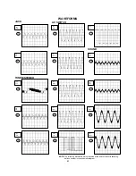
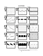
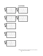
Page 87: ...corresponding balloon number in the schematic diagram NOTE 4 2ms 0 5V 5 2ms 0 5V 6 2ms 200mV 7 8 9 2ms 200mV 2ms 200mV 2ms 200mV 10 0 5ms 1 0V 11 50μs 1 0V 12 2ms 50mV SOUND 13 14 1ms 200mV 15 2ms 50mV 1ms 200mV 1 2ms 0 5V JACK 2 2ms 0 5V 3 10μs 0 5V TUNER STEREO AV SWITCH ...

Page 88: ...lloon number in the schematic diagram NOTE 16 20 50ns 500mV 20μs 500mV 21 22 20μs 500mV 20μs 500mV MICON 24 23 10μs 2 0V 20μs 500mV 25 10ms 100mV LVDS 17 19 10μs 100mV 10μs 100mV 18 10μs 200mV SCALER MPEG MICON DSP RF_AMP 51 10ns 100mV 52 5ns 20mV 53 20ns 1 0V 28 2ms 50mV SOUND 31 2ms 50mV ...

Page 89: ... balloon number in the schematic diagram NOTE AUDIO VIDEO 56 57 500μs 500mV 500μs 500mV 59 10μs 200mV 60 10μs 200mV 62 61 2μs 2 0V 2μs 2 0V REGULATOR 2 70 10μs 2 0V 71 10μs 2 0V 72 10μs 2 0V 73 10μs 2 0V 75 10μs 5 0V 74 10μs 5 0V 76 10μs 50 0V INVERTER 54 200ns 1 0V 55 5ns 500mV MEMORY ...

Page 90: ...MS The following waveforms were measured at the point of the corresponding balloon number in the schematic diagram NOTE 79 10μs 50 0V 80 10μs 500V 81 10μs 500V 82 10μs 500V 83 10μs 500V 78 10μs 50 0V 77 10μs 50 0V ...

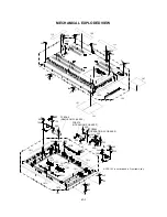
Page 91: ...21 101A 101C 101D 202 101B 202 101E 101F 101H 101G 101E 101I 101I 101J 101 202 101J 202 202 123 202 PCBDA0 REMOCON PCB ASS Y 202 124 PCB270 OPERATION PCB ASS Y 202 PCB280 OPERATION 2 PCB ASS Y 105 105 202 202 125 202 125 202 125 202 125 202 202 202 153 153 153 138 138 NOTE 153 is not included in Front cabi Ass y ...

Page 92: ...39 137 202 PCBDS0 SCALER PCB ASS Y 206 206 211 211 NOTE 104 is not included in Stand Ass y 106 PCBD90 SIDE JACK PCB ASS Y 133 206 115 206 206 130 129 206 206 206 206 206 206 118 118 206 119 207 207 207 PCB350 BACK LIGHT PCB ASS Y 207 116 206 206 117 135 206 139 135 206 135 138 PCB130 DVD MT PCB ASS Y 106 106 106 206 128 206 206 112 113 131 114 132 206 206 206 206 212 208 208 206 206 206 PCBD20 AV ...

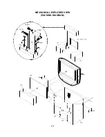
Page 93: ...MECHANICAL EXPLODED VIEW PACKING DIAGRAM J1 3 143 143 146 140 141 142 142 149 150 151 152 144 145 147 CD3811 TM101 148 AD001 BL001 140 ...

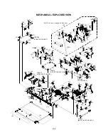
Page 94: ...r more If the repair is needed replace the DVD MECHA ASS Y PCB640 SW PCB ASS Y 701 702 702 607 604 CD2001 603 M2602 606 602 704 703 605 SW2 705 CD2301 AA 703 703 605 601 608 608 600 Applying positions AA for the grease are displayed for this section Check if the correct grease is applied for each position NOTE CLASS GREASE MARK AA ...

Page 95: ...ET RATING 108 AE008472 752WSA0596 SHIELD SCALER 109 AE008464 7230008127 SHEET JACK 2 110 AE008465 7230008128 SHEET JACK SIDE 111 AE008466 7230008188 SHEET JACK 1 112 AE005122 726000A073 SHEET CAUTION 113 AE008467 752WSA0577 SHIELD JACK 1 114 AE008468 752WSA0578 SHIELD JACK 2 115 AE008469 752WSA0579 SHIELD JACK SIDE 116 AE008678 752WSA0607 SHIELD MPEG 117 75003866 752WSA0612 SHIELD FFC 118 AE007881...

Page 96: ...K E 152 AE009352 J5X00410A INSTRUCTION BOOK F 153 AE001213 800WB0A008 FIBER WASHER 201 AE005140 810A14080U SCREW WASHER A M4 8 CH 202 AE003528 8110630A0U SCREW TAP TITE P BRAZIER 3 10 CH 203 AE003524 8109I30A0U SCREW TAP TITE B WH7 3 10 CH 204 AE007747 814623080U SCREW TAP TITE B BIND 3 5 7 4 2 3 CH 205 AE007748 810A13050U SCREW WASHER A M3 5 CH 206 AE003526 810923080U SCREW TAP TITE B BIND 3 8 CH...

Page 97: ...07 AE005816 92P100116A GEAR FEED 608 BZ710149 800WFAA008 CUSHION C 701 AE005817 92P700007A SCREW GEAR FEED 702 AE003554 814011723U SCREW PAN M1 7 2 3 P3 CH 703 AE003555 816112080U SEMS TAP TITE P PAN W10 2 8 CH 704 AE005006 813381750U SCREW T TITE B CAMERA PAN M1 7 5 0 P3 CH 705 AE003557 811022080U SCREW TAP TITE P BIND 2 8 CH CD2001 AE008502 122J4O1603 CORD JUMPER 127000 2933 CD2301 AE003558 122H...

Page 98: ... BZ410086 DD7R0S3550 DIODE SILICON 1SS355 TE 17 D4008 BZ410086 DD7R0S3550 DIODE SILICON 1SS355 TE 17 D7001 BZ410086 DD7R0S3550 DIODE SILICON 1SS355 TE 17 D7002 BZ410086 DD7R0S3550 DIODE SILICON 1SS355 TE 17 D7003 AE008428 DD7PN202U0 DIODE SILICON DAN202UT106 D7004 AE008428 DD7PN202U0 DIODE SILICON DAN202UT106 D7005 AE008428 DD7PN202U0 DIODE SILICON DAN202UT106 D7006 AE008428 DD7PN202U0 DIODE SILIC...

Page 99: ...MPOUND TRANSISTOR KRC102SRTK Q3809 AE007842 TJ7M50P030 FET RSS050P03_TB Q4201 BZ510109 TCAA3875SY TRANSISTOR SILICON KTC3875S_Y_RTK Q4202 BZ510109 TCAA3875SY TRANSISTOR SILICON KTC3875S_Y_RTK Q4203 BZ510109 TCAA3875SY TRANSISTOR SILICON KTC3875S_Y_RTK Q4204 BZ510109 TCAA3875SY TRANSISTOR SILICON KTC3875S_Y_RTK Q4205 BZ510113 T27T030180 FET 2SK3018T106 Q4206 BZ510113 T27T030180 FET 2SK3018T106 Q430...

Page 100: ...0 AE008424 A5X002BD90 SIDE JACK PCB ASS Y CEF177B PCBDA0 AE008425 A5X002BDA0 REMOCON PCB ASS Y CEF176B PCBDS0 AE009345 A5X004BDS0 SCALER PCB ASS Y CEF174A MISCELLANEOUS AD001 AE007897 0411030096 AC ADAPTER 11030096 B801 AE007761 024AC5181J CORE BEADS BLM18PG181SN1D B802 AE007761 024AC5181J CORE BEADS BLM18PG181SN1D B803 AE008395 024HC56005 CORE BEADS FCM1608CF 600T06 B804 AE007761 024AC5181J CORE ...

Page 101: ...U20001A CP2201 AE008407 06CU230703 CORD CONNECTOR CU230703 CP2202 AE005289 06CU220702 CORD CONNECTOR CU220702 CP2204 AE005065 06CU252001 CORD CONNECTOR CU252001 CP2251 AE005287 069S220639 CONNECTOR PCB SIDE A2001WR2 2P CP2301 AE008156 069KYOT159 CONNECTOR PCB SIDE LD07T2 24ND 03 CP2302 AE005934 069EV53030 CONNECTOR PCB SIDE 00_6232_005_006_800 CP2303 AE005935 069EV63030 CONNECTOR PCB SIDE 00_6232_...

Page 102: ...AE007784 100YT05401 CRYSTAL FCX 03 X4001 AE008161 100GT02720 CRYSTAL B27000C005 RESISTOR RC CARBON RESISTOR CAPACITORS CC CERAMIC CAPACITOR CE ALUMI ELECTROLYTIC CAPACITOR CP POLYESTER CAPACITOR CPP POLYPROPYLENE CAPACITOR CPL PLASTIC CAPACITOR CMP METAL POLYESTER CAPACITOR CMPL METAL PLASTIC CAPACITOR CMPP METAL POLYPROPYLENE CAPACITOR K3 5 ...

Page 103: ...TOSHIBA CORPORATION 1 1 SHIBAURA 1 CHOME MINATO KU TOKYO 105 8001 JAPAN ...

Reviews: