background image

17

1600Xp Series installation and operation manual

UPS LAN Shutdown Signal Operation 

when the UpS stop signal is sent to the UpS through pin 2 and 3 of the external contact interface, it is 

possible to automatically reset the following operating systems (oS), which can automatically implement 

the shutdown function and restart the operation:  

Windows NT, IBM OS/2 LAN server, LANtastic

parameter 646 – UpS Shutdown by lAn input Signal enabled/disabled
parameter 647 – UpS Shutdown by lAn Signal permitted time window (Adjustable)
with the 

UPS Shutdown by LAN Signal

 function enabled, when line power fails and the UpS goes to 

backup the lAn will shutdown even if the UpS returns to normal mode during the shutdown process.  
lAn shutdown can take several minutes.  the 

UPS Shutdown by LAN Signal

 function has a companion 

UPS Shutdown by LAN Signal Permitted Time Window

 parameter that can be set to allow sufficient 

time to complete the lAn shutdown process (default: 10 minutes) even if line power is restored during 

lAn shutdown.
lAn shutdown is treated as a restart after battery shutdown.  the restart of the lAn will be determined 

by the 

Restart After Battery Shutdown 

timer.

Connect only the UpS stop signal to the external contact interface for automatic processing so that the 

UpS output will not be turned off by mistake. 

If the computer is started/restarted within 10 minutes after the recovery from a power failure, the 

power supply may be reset while the computer is restarting.

Summary of Contents for 1600XP SERIE

Page 1: ...ower System UPS Part 60616 005 April 2011 Manufactured in the USA Copyright 2011 TOSHIBA International Corporation All rights reserved 1600XP SERIES Installation and Operation MANUAL Single Phase 3 6 6 8 10 14 18 22 kVA ...

Page 2: ...1600XP Series Installation and Operation Manual ...

Page 3: ...1600XP Series Installation and Operation Manual Uninterruptible Power System UPS Installation and Operation MANUAL Single Phase 3 6 6 8 10 14 18 22 kVA Part 60616 005 April 2011 1600XP SERIES ...

Page 4: ...iations in equipment or to provide for every possible contingency concerning installation operation or maintenance Should further information be required or if problems arise which are not covered sufficiently contact your Toshiba sales office The contents of this instruction manual shall not become a part of or modify any prior or existing agreement commitment or relationship The sales contract c...

Page 5: ...he warranty period for the UPS or UPS part is 36 months from the shipment date see Toshiba International Corporation bill of lading Unless otherwise specified the warranty period for a UPS battery is 24 months from the shipment date see Toshiba International Corporation bill of lading JOB NUMBER MODEL NUMBER SERIAL NUMBER APPLICATION SHIPMENT DATE INSTALLATION DATE INSPECTED BY ...

Page 6: ... trade references appearing in this manual are registered trademarks of their respective owners Toshiba International Corporation shall not be liable for direct indirect special or consequential damages resulting from the use of the information contained within this manual This manual is copyrighted No part of this manual may be photocopied or reproduced in any form without the prior written conse...

Page 7: ...ction 6 Storage 6 Disposal 6 Installation Precautions 7 Conductor Routing and Grounding 9 Operating Precautions 9 Equipment Warning Labels 10 UPS Connections 13 Terminal Block 13 Wire Size and Tightening Torque 14 Communication Interfaces 16 UPS LAN Shutdown Signal Operation 17 RS 232C 18 RemotEye III Network Card 18 UPS Specifications 19 Operating the UPS 25 Initial Startup First Power Up 25 Batt...

Page 8: ...2 Settings Parameters 46 Records 61 System Fault Messages 62 System Warning Messages 63 System Mode Messages 65 System Status Messages 65 UPS Protection System 67 System Protection Features 67 System Protection Functions 67 Preventive Maintenance Parts Replacement 68 Preventive Maintenance 68 Cleaning the Touchscreen 68 Parts Replacement 69 Optional Receptacle Panel Installation Instructions 69 Op...

Page 9: ... When symbols are used in this manual they will include important safety information that must be carefully followed Safety Alert Symbol indicates that a potential personal injury hazard exists Prohibited Symbol indicates DO NOT take action Mandatory Symbol indicates that the following instruction is required Ground Symbol indicates the location of the equipment grounding conductor Electrical Volt...

Page 10: ...ce may not cause harmful interference 1 This device must accept any interference received including interference that may cause undesired 2 operation Notice The FCC regulations provide that changes or modifications made to this device that are not approved by Toshiba International Corporation may void the authority granted to the user by the FCC to operate this equipment EMC Directive Class A Note...

Page 11: ... an 2 output disconnect for the AC output Therefore a user installed circuit breaker should be provided between the UPS output and the load input The 3 maximum ambient operating temperature is 104 F 40 C Access panels should only be removed by authorized Toshiba field Service personnel 4 UPS servicing should be performed by qualified Toshiba representatives only 5 Battery servicing should be perfo...

Page 12: ...ther metal objects 2 Use tools with insulated handles to prevent inadvertent shorts 3 Wear rubber safety gloves and boots 4 DO NOT place tools or any metal parts on top of batteries 5 Determine if the battery is inadvertently grounded If inadvertently grounded remove source of 6 ground Contact with any part of a grounded battery can result in electrical shock The likelihood of shock will be reduce...

Page 13: ...a compact high performance and energy efficient unit The UPS unit assures safe and reliable operation of critical office equipment All units feature an audible alarm which sounds if the battery voltage drops below a specified minimum during use This is an additional aid to help protect valuable office data banks All units allow for computer interfacing Output Rating Toshiba 1600XP Series 208 240V ...

Page 14: ...esults store the UPS in the original shipping container and place on a wood or metal pallet Storage temperature 4 104 F 20 40 C The optimum storage temperature is 70 F 21 C A higher ambient temperature will require recharging more frequently during storage Avoid storage locations that Are subject to extreme temperature changes or high humidity Are subject to high levels of dust or metal particles ...

Page 15: ...t least 4 inches 100 mm clearance on all sides of the ups 3 for air ventilation Follow the instructions on the unpacking label affixed to the exterior of the UPS 4 teries esult s and or must be nician WARNING CRITICAL FUSE SIZING incorrect fuse replacem ent size may result in fire or inadequate equipm ent protection re pla ce only with same type and rating of fuse 49455 SHEET CAUt ion At te nt ion...

Page 16: ...pt one that has an auxiliary contact that in all cases causes switching devices to break the load circuit before the opening of the main contacts of the disconnector A circuit breaker suitable as an isolation device per IEC 60947 2 Any other switching device in accordance with an IEC product standard that also meets the isolation requirements of IEC 60947 1 and is appropriate for on load switching...

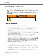
Page 17: ...tarting current or with motors that require a long starting time such as vacuum cleaners and machine tools oversizing the UPS for lock rotor current would be required DO NOT insert metal objects or combustible materials in the 5 ventilation slots of the UPS DO NOT place hang or paste any objects on the exterior surfaces of the UPS 6 The capacitors of the UPS maintain a residual charge for a while ...

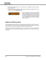
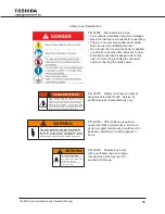
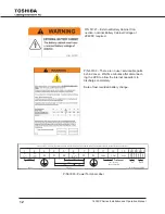
Page 18: ...the load The unit must be in the bypass mode at the time that the breaker is placed in the OFF position for the UPS to shutdown power to the load Equipment Warning Labels The following pages show examples of warning labels that may be attached to either the interior or ex terior of the UPS Do not remove or cover any of the labels If the labels are damaged or if additional labels are required conta...

Page 19: ...ected Capac itorsstore hazardous energy do not rem ove cover until 5 minutes after disconnecting all sources of supply battery backup time which wasfactory set at a predetermined level decreases gradually between service periods t he batteriesshould be replaced every three years after the last servicing the date of which is written on the id plate located on the rear side of the U pSunit or in the...

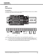
Page 20: ...Y WIRED FOR 208V INPUT o 208 240V 208V 120V 240V 120V INPUT VOLTAGE JUMPER SELECTION EPO REMOTE INPUT OUTPUT FOR SINGLE HOT WIRE P N63093 Power Terminal Label P N 63109 There are no user serviceable parts behind cover Wait five minutes after disconnect ing the UPS to allow the internal capacitors to discharge completely Date of last recorded battery change P N 51727 External Battery Cabinet Con ne...

Page 21: ...Vac rated short terminals 11 and 12 with a jumper wire DO NOT jumper terminal 13 to 12 or 11 Factory Setting is 208Vac Use the jumper wire provided by Toshiba DO NOT add any additional jumpers Note 2 If AC input power is 240 Vac rated short terminals 12 and 13 with a jumper wire DO NOT jumper terminal 11 to 12 or 13 Use the jumper wire provided by Toshiba DO NOT add any additional jumpers 240V 208...

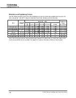
Page 22: ...2 kVA AC Input Lines 1 and 2 10 8 8 8 8 1 0 6 1 0 4 1 0 1 1 0 14 2 1 56 AC Output Lines 4 5 and 7 12 8 10 8 8 1 0 6 1 0 4 1 0 1 1 0 14 2 1 56 AC Output Neutral 6 12 8 10 8 8 1 0 6 1 0 4 1 0 1 1 0 14 2 1 56 Ground 3 and 8 12 8 10 8 8 1 0 6 1 0 4 1 0 1 1 0 14 2 1 56 EPO Switch 14 and 15 16 16 16 16 16 16 9 0 0 99 Remote Switch 16 and 17 16 16 16 16 16 16 9 0 0 99 Note Wire size is presented as the r...

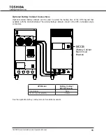
Page 23: ...nd the backup time of the UPS beyond that available with the internal batteries The external battery cabinets connect to the UPS via Anderson style connectors mCCb battery Cabinet main Circuit breaker UPS Model Battery Cabinet MCCB Capacity 3 6 6 kVA 50 A 8 10 14 18 22 kVA 100 A See the applicable battery cabinet manual for additional details ...

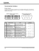
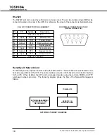
Page 24: ...30 Vac rms 42 Vac peak 50 mA rms 70 mA peak Pin Signal Function Logic In the UPS 1 Fault Signal Closed when fault detected 2 UPS stop common Backup stop when the level changes from Low 3 to 15 V to High 3 to 15 V 3 UPS stop signal input 4 Normal input power supply Closed with normal supply power 5 Signal common Common signal return 6 Bypass operation Closed during bypass operation 7 Battery voltag...

Page 25: ...l shutdown even if the UPS returns to normal mode during the shutdown process LAN shutdown can take several minutes The UPS Shutdown by LAN Signal function has a companion UPS Shutdown by LAN Signal Permitted Time Window parameter that can be set to allow sufficient time to complete the LAN shutdown process default 10 minutes even if line power is restored during LAN shutdown LAN shutdown is treat...

Page 26: ...nal ready 5 SG Signal ground 6 Input DSR Data set ready 7 Output RTS Request to send 8 Input CTS Clear to send 9 This pin is not used RemotEye III Network Card The RemotEye III is an optional network card for the Toshiba UPS This card slides into a slot located on the back side page 65 66 of the UPS The card provides a network or LAN based communication interface for the UPS When installed the UPS...

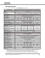
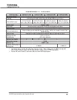
Page 27: ... Time 24 hr full 12 hr 90 for internal batteries only3 Battery Voltage Nominal 144 Vdc 216 Vdc 288 Vdc Output Characteristics Output Voltage Single phase 240 208 120 V Output Voltage Regulation 3 Output Frequency 0 5 Hz 1 0 Hz 1 5 Hz factory or authorized service center selectable only AUTO MAN Frequency Factory or authorized service center selectable only Voltage THD 3 for linear load 6 for non l...

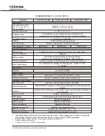
Page 28: ...p 32 Warnings 32 Faults 32 Test 32 System Applications Switches Generator compatible Bypass Switch Bypass Disable Static switch cycle 50 Hz 5 ms 60 Hz 4 16 ms Automatic Retransfer Factory or authorized service center selectable only Interface Communications Real Time Clock Real Time Clock with backup Lithium Ion Battery Schedule Operation Schedule ON OFF operation of UPS using optional RemtoEye II...

Page 29: ...attery System Battery Replacement Slide out battery packs accessible from front of UPS Factory or authorized service center serviceable only Battery Packs Designed for battery acid leakage containment with six 6 batteries per pack Battery Pack Size HxWxD max 5 0 x 7 3 x 19 0 in 127 x 185 x 483 mm Battery Pack Quantity 2 3 4 Battery Manufacturer YUASA Battery Type REW45 12FR Toshiba s Part Number f...

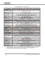
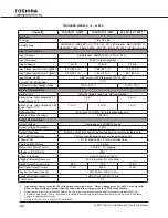
Page 30: ...Output Characteristics Output Voltage Single phase 240 208 120 volts Output Voltage Regulation 3 Output Frequency 0 5Hz 1 0Hz 1 5Hz factory authorized service center selectable only AUTO MAN Frequency Factory or authorized service center selectable only Voltage THD 3 for linear load 6 for non linear load Common Mode Noise 5 Vrms Rated Load Power Factor1 0 85 0 6 1 0 lagging Efficiency AC DC AC 86 ...

Page 31: ... System Applications Switches Generator compatible Bypass Switch Bypass Disable Static switch 1 4 cycle 50Hz 5 ms 60Hz 4 16 ms Automatic Retransfer Factory or authorized service center selectable only Interface Communications Real Time clock Real Time Clock with backup Lithium Ion Battery Schedule Operation Schedule ON OFF operation of UPS using optional RemotEye III communication software Autosta...

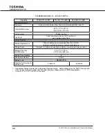
Page 32: ... battery packs accessible from front of UPS factory or authorized service center serviceable only Battery Packs Designed for battery acid leakage containment with 6 batteries per pack Battery Pack Size HxWxD max 5 0 x 7 3 x 19 0 in 127 x 185 x 462 mm Battery Pack Quantity 8 Battery Manufacturer YUASA Battery Type REW45 12FR Toshiba Part Number for Battery Pack 51896 FS 60995 FS Input output figure...

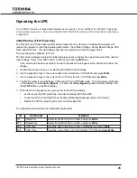
Page 33: ...the display Repeat the process in step 1 in selecting the Rated Output Voltage 1 Use the keypad to type in the current date in the format 2 Mon 10 05 2009 and press Write Use the keypad to type in the current time in 12 hour format 3 12 15 PM and press Write The Main screen is now displayed Verify the UPS is in BYPASS mode The mode lower right side 4 of the display should display Bypass If it does...

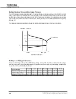
Page 34: ...llustration graphically shows the battery discharge process at full load conditions Battery Low Voltage Tolerances Excessive discharge will cause the UPS battery voltage to drop The chart shown below lists the voltage level at which each UPS low voltage alarm will sound and at what level the low voltage condition will cause the unit to automatically shut down UPS Capacity 3 6 kVA 6 kVA 8 kVA 10 kV...

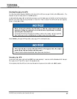
Page 35: ...teries for at least 24 hours input breaker on before operating the connected load Using the UPS without charging the battery shortens the battery backup operation time which may result in the destruction of data in case of a power failure Press RUN key to begin UPS operation see page 37 for startup screens NOTICE If the input breaker is turned off while UPS is in the bypass state the output power ...

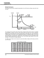
Page 36: ...charge to their normal fully charged state In the third period a slight trickle current continues to flow into the batteries to keep them fully charged and floating at the normal Vdc level A full recharge usually requires 24 hours 90 recharge in 12 hours after a complete discharge The following chart shows the rated maximum and minimum battery voltages and the charge current for each of the sizes ...

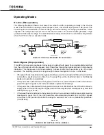
Page 37: ...t overload condition ends within a specified period of time then the power flow will be transferred back to the On Line mode run operation automatically If the power flow is transferred to the bypass circuit due to an external fault the UPS will shut down power through the bypass to the load and indicate a system fault message If the power flow is transferred to the bypass circuit due to an intern...

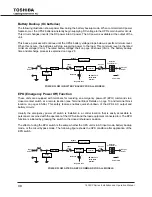
Page 38: ... and terminal block location on pages 65 66 This safety feature enables quick shut down of the UPS s AC output and battery circuits Usually the emergency power off switch is installed in a central location that is easily accessible to personnel concerned with the operation of the UPS unit and the load equipment connected to it The EPO function is initiated by pressing the switch to the closed shut...

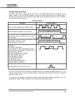
Page 39: ...att Voltage 79 Normal Warnings OL110 Overload Timer LB Low Battery Batt Voltage 90 Normal BLFN Battery Life Pre alarm Batt exp in 6 mo BLFE Battery Life End CHRGOV Charger Over Voltage BTSTFL Battery Test Fail BOH Battery Overheat AOH Ambient Overheat CLMT Current Limit DCER Display Disconnected BDEPL Battery Depletion Touching Effective Item on Touchscreen The buzzer can be silenced by selecting ...

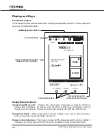
Page 40: ...ch When necessary the touchscreen display can be reset by using a thin probe such as a paper clip to press the display reset switch Display Contrast Adjustment The display is shipped with the display adjusted for optimum visibility If necessary use a trimmer adjustment tool to fine tune the display contrast for improved visibility Display contrast adjustment middle left side of panel LCD touch scr...

Page 41: ...y Information UPS System Status and System Time At the top left of the display are a bank of four touch sensitive keys Home Pressing HOME key returns the display to the top menu of the currently selected tab Security Level Pressing the Security Level key activates the log in security screen Speaker Pressing the Speaker key will disable enable the audible alarm Touchscreen Lock Locks touchscreen ex...

Page 42: ... disappear from the RUN key Home Key Press to return to top menu of respective tab Security Level Key Press to open security login screen Event Alarm Mute Key Press to silence current event alarm Alarm Muted Key Alarm remains silenced until next event Touchscreen Enabled Key Press to disable lockout all touchscreen keys except this key Touchscreen Disabled Key Press to enable un lock touchscreen F...

Page 43: ... Code For a detailed listing see page 54 On Line Current operating mode of the UPS For a detailed listing see page 56 Light Emitting Diodes LED The following table describes the front panel LED behaviors and the associated meaning LED Behavior Significance Meaning Green ON UPS is in On Line Backup or Battery Test mode Green OFF UPS in Bypass mode Green OFF UPS in shutdown mode Red ON One or more f...

Page 44: ...put IN Output OUT Bypass BYP Battery BAT and DC Bus DC Control Configura tion C C and Display External D E devices SETTINGS Allows monitoring and or modification of UPS pa rameters Parameters that can be viewed or modified vary depending on the security level of the login password entered using keypad Records Displays the most re cent 32 Test Backup Faults Warning Operation and System change recor...

Page 45: ...uchscreen lockout key is disabled when the screen is in keypad mode The Lockout key will change to and the touch screen will not respond to any input except a touch to the lockout key Touching the lockout key again will toggle the lockout off the graphic will change to indicating the touch screen is active Main Screen On Line DVCOH ASYN 1600XP On Line UPS UPS Serial Number 20080112345 UPS Typeform...

Page 46: ...s as above The Space key is used to enter a space between alpha numeric characters Example By using the additional characters available with the shift key you can type in a device name Toshiba H3 instead of TOSHIBAH3 Return to the Upper Case format keypad by pressing Shift again Exit the keypad display by pressing either the Quit or Write key On Line DVCOH ASYN Main Monitor Settings Records 12 35 ...

Page 47: ...o User USER Administrator ADMIN Typing in USER in the keypad will change the se 3 curity level to User Enter the password using the alphanumeric keys Press 4 Write to store the password in the UPS If the password is accepted the text Successful will display at the bottom left of the touchpad as shown here If the password entered was not accepted the text Error15 Write Function or some similar mess...

Page 48: ...owing The Monitor display below shows the UPS in Shutdown Mode Power is flowing to charge the battery but no power is going to the Bypass or Output Monitor Details Press the IN BYP OUT DC or BAT key on the mimic display to view the parameter details for that section of the UPS The MONITOR TAB figure on the following page shows the relationship of the various data displays Press the Home key Home t...

Page 49: ...s Records 12 35 PM INV HOME USR BAT 1 1 501 Battery Voltage 503 Discharge Current 506 Charger Status 508 Cal Battery Vsd 547 Cal LB Level 200 Vdc 0 0 Adc Normal 172 Vdc 194 Vdc On Line DVCOH ASYN Main Monitor Settings Records 12 35 PM INV HOME USR OUT 1 2 201 Output Config 203 Output Voltage 204 Output Current 205 Output Frequency 206 Output Power W 207 Output Power VA 7 234 v 21 4 A 60 0 Hz 4590 ...

Page 50: ...y current power over under voltage settings Bypass 300 399 Bypass data such as configuration voltage current power OV detection level DC Bus 400 499 Data such as Total voltage rated voltage Positive and Negative bus voltages Batt 500 599 Battery voltage charger status total discharges shutdown voltage Ctrl Cfg 600 699 Control and configuration list system and battery temperatures system status sta...

Page 51: ...el 141 Freq on FIERR 1 Line 240 V 274 V 264 V 50 0 Hz On Line DVCOH ASYN Main Monitor Settings Records 12 35 PM FLT HOME USR DC 1 1 404 Rated DC Bus 770 Vdc On Line DVCOH ASYN Main Monitor Settings Records 12 35 PM FLT HOME USR HIS 1 4 701 System Op Time 702 Inverter Op Time 703 Backup Op Time 704 UPS Lifetime 705 Hi System Temp 706 Hi Battery Temp 07031 Sec 0 Sec 0 Sec 6118 Hr0 28 C 8 C output Bl...

Page 52: ...nge Press the Rated Vin pa rameter listing and enter the correct value in the Active Value box using the standard alphanumeric keypad Use the back arrow to delete an incorrect keystroke After changing the parameter value press Write to write the entered value to the UPS memory Some parameters are informational some can be changed by the user and others can only be changed by a higher security acce...

Page 53: ...y will switch to the C 7 alibration Screen shown below Gently press a stylus or similar fine pointed tool to the center of the 8 X located at the top left hand side of the display As soon as the information is read a second X will be displayed at 9 the top right hand of the display Repeat Step 7 Repeat Step 7 for X displayed at the lower right hand side of the 10 display Repeat Step 7 for the X di...

Page 54: ... Display text often abbreviated Brief Description Brief description of the function of the parameter Location Map Tab Blk Gives the menu location for the parameter by Tab and Block The tabs are Main Monitor Settings Records E g Cmd 501 Battery Voltage can be viewed under the Monitor tab in the BATT block UPS Status is displayed in the display header Status field UPS Faults and Warnings are shown i...

Page 55: ...006 Main BLoader Ver Main Bootloader Version The last 5 digit represents Main Controller s Bootloader software version In this example the version is 1 000 Settings ID UH3MBL01000 Nonchangeable Nonchangeable User Administrator 007 Job No Job Number Toshiba s manufacturing job number Settings ID JB0123456789 Nonchangeable Nonchangeable User Administrator 008 Test Person Test Person s First and Last...

Page 56: ...angeable User Administrator 107 Input Power VA Input Apparent Power UPS presently calculated input apparent power input voltage input current Monitor IN 6000 VA Nonchangeable Nonchangeable User Administrator 108 Input PFactor Input Power Factor If converter is not running display shows N A Monitor IN 1 0 Nonchangeable Nonchangeable User Administrator 111 Rated Vin Rated Input Voltage Used to calcu...

Page 57: ...ting IN 60 0 Hz Nonchangeable Changeable User Administrator 201 Output Config Output Configuration Displays the voltage and frequency 240 V 60 Hz or 208 V 60 Hz Monitor OUT 240V 60Hz Nonchangeable Nonchangeable User Administrator 202 No of Output Line No of Output Lines Always 1 input line for 1600XP series Setting OUT 1 Line Nonchangeable Nonchangeable User Administrator 203 Output Voltage Output...

Page 58: ... User Administrator 219 Rated Pout VA Rated Output Apparent Power Calculated from typefrom command ID 002 Monitor OUT 6000 VA Nonchangeable Nonchangeable User Administrator 220 VOUV De Level Output Undervoltage Detection Level in Per centage Of rated output voltage which was configured with Command ID 215 Setting OUT 90 Nonchangeable Nonchangeable User Administrator 222 VOOV De Level Output Overvo...

Page 59: ...overy Level in per centage Of rated input voltage command ID 111 Setting BYP 66 Nonchangeable Nonchangeable User Administrator 317 VBypOV De Level Bypass Over Voltage Detection Level in Volt Setting BYP 284 V Nonchangeable Nonchangeable User Administrator 318 VBypOV ReLevel Bypass Over Voltage Recovery Level in Volt Setting BYP 274 V Nonchangeable Nonchangeable User Administrator 401 DC Bus Total ...

Page 60: ...ministrator 511 Rated Ahr Rated Battery Ampere Hour One of the battery s properties Settings BATT 9 AHr Nonchangeable Nonchangeable User Administrator 512 No Batt Series Number of Battery in Series Settings BATT 18 Nonchangeable Nonchangeable User Administrator 513 No Batt Paral Number of Battery in Parallel Settings BATT 1 Nonchangeable Nonchangeable User Administrator 514 Batt Ins Date Battery i...

Page 61: ...rature Measured on control PCB Monitor C C 26 C Nonchangeable Nonchangeable User Administrator 602 Battery Temp Battery Temperature Measured on battery tray Monitor C C 25 C Nonchangeable Nonchangeable User Administrator 608 Current State Current UPS State Footer Monitor Right C C On Line Nonchangeable Nonchangeable User Administrator 609 Requested State Requested UPS State Main Settings RUN STOP ...

Page 62: ...attery Backup Follow the same format as display shows Mon 10 05 2009 Settings C C Mon 10 05 2009 Changeable Changeable User Administrator 635 UPS Time UPS Real Time Battery Backup Use the same format as display shows 12 hour format Settings C C 11 46 AM Changeable Changeable User Administrator 636 Timestamp UPS Real Time Date and Time Stamp Used for recording feature Monitor C C 0X268AB487 Nonchan...

Page 63: ...p Non volatile configuration Time delay for Backup dry contact will be on after UPS goes to Backup Mode Default from factory is 10 Sec Settings C C 10 Sec Nonchangeable Changeable User Administrator 649 LB DContact Delay Time Delay Remote Contact On Low Battery Non volatile configuration Time delay for Low Battery dry contact will be on after UPS detects Low Battery warning Default from factory is...

Page 64: ... is 57600 Settings C C 57600 Nonchangeable Changeable User Administrator 682 Special Purpose Call Factory for Further Information Settings C C Nonchangeable Nonchangeable User Administrator 693 Invert Rmt SDown Remoted Shutdown Inverted Logic Non volatile configuration Default from fac tory is Normally Open Settings C C Normally Open Nonchangeable Changeable User Administrator 695 Restart Mode Res...

Page 65: ...fac tory is 0 Settings HIST 0 Nonchangeable Nonchangeable User Administrator 709 Total Tests Total No Of Tests Non volatile history record Default from fac tory is 0 Settings HIST 0 Nonchangeable Nonchangeable User Administrator 710 Test Record Test Record Detail View at Record Tab Settings HIST Nonchangeable Nonchangeable User Administrator 711 Total Backups Total No Of Backup Non volatile histor...

Page 66: ...geable User Administrator 802 DFW BDate Display Build Date Settings D R Sep 30 2009 Nonchangeable Nonchangeable User Administrator 803 DFW BTime Display Build Time Settings D R 16 45 42 Nonchangeable Nonchangeable User Administrator 804 DBS Ver Display Bootsector Version Settings D R UH3DBS01000 Nonchangeable Nonchangeable User Administrator 805 DBL Ver Display Bootloader Version Settings D R UH3D...

Page 67: ...e the user through those commands necessary to setup the UPS properly Settings D R Disable Nonchangeable Changeable User Administrator 839 Test Result Displays results of selected system test Settings D R Nonchangeable Nonchangeable User Administrator 850 Reye Ins Dat DC Monitor D R Nonchangeable Nonchangeable User Administrator 851 Reye Ver RemotEye Firmware Version Monitor D R Nonchangeable Nonc...

Page 68: ...ud Rate Non volatile configuration Default from fac tory is 57600 Settings D R 57600 Nonchangeable Changeable User Administrator 857 SReye Datlink Status of Remote Eye s Data Link UPS Un known Idle OK Monitor D R Unknown Idle OK Nonchangeable Nonchangeable User Administrator 858 SReye Netlink Status of Remote Eye s Network Link Un known Idle OK Monitor D R Unknown Idle OK Nonchangeable Nonchangeab...

Page 69: ...35 PM INIT HOME USR 1 2 Backup Record Rec No 2 Date 04 15 09 Sin 240 60Hz Vin 24 Iout 84 Vbst 92 Backup 140 s Trigger source ViVU Time 10 17 29 Sout 240 60Hz Vout 98 Vdc 101 Vbend 92 On Line DVCOH ASYN Main Monitor Settings Records 12 35 PM INIT HOME USR 1 16 Fault Record Rec No 803 Date 04 14 09 Sin 240 60Hz Vin 99 Iout 89 Vbst 92 VOUV Time 12 54 17 Sout 240 60Hz Vout 98 Vdc 101 On Line DVCOH ASY...

Page 70: ...on conditions at time of fault Not advisable to restart the UPS Call for service CLMT Current Limit Load on UPS out put exceeds unit specifications Reduce load on UPS output DCIB DC Bus Imbalance DC voltage imbalance occurred Possible causes are UPS fault are connection of half wave rectifier load Check load and try restarting If condition persists call for service DCOC DC Bus Overcurrent DC overc...

Page 71: ...es and exceeds 50 C ambient Check to see if the ambient temperature is greater than 104 F 40 C If so turn on air conditioning and check the ventilation fan at the back of the unit for operation or obstructions Otherwise shut down the unit and call for service ASYN Asynchronous mode Input and output frequency are different Bypass is disabled No Action Needed BDEPL Battery Depleted Battery not withi...

Page 72: ... on UPS mode LB Low Battery The battery level has dropped low about 90 or less during operation Continued operation in this mode will deplete battery and cause output shut down Immediately shut down the load equipment in an orderly fashion and then press the STOP key OL110 Overload UPS is overloaded 110 and above Unit will switch to bypass operation or shut down if no action is taken Shut down exc...

Page 73: ...ion needed CHRGERR Charger Error Charger overvoltage error Contact the nearest Toshiba autho rized representative for service DLYST Delay Start UPS is counting down prior to startup No action needed EE1ST EEPROM is loaded with default values No action needed EE2RAERR EEPROM to RAM loading Error Contact the nearest Toshiba autho rized representative for service EEUPERR EEPROM updating Error Contact...

Page 74: ...ion and then press the STOP key PFAIL Input power failure No action needed RMTSD Remote shutdown occurred Disconnect LAN signal to reset RO2EEERR ROM to EE Loading Error Contact the nearest Toshiba autho rized representative for service SYNC Synchronous mode Input and output are synchronized TIMEDSD UPS is counting down prior to shutdown Immediately shut down the load equipment in an orderly fashi...

Page 75: ...lt Bypass operation Chopper and inverter are stopped Inverter OL Transfer to bypass Bypass OL Inverter chopper stopped Audible Alarm Yes Continuous buzzer See Audible Alarm Functions on page 31 Visible Alarm Red Fault LED on Inverter OL Fault lamp off Bypass OL Fault lamp on Relay Contact Alarm Fault relay closed Bypass relay closed Fault relay open Inverter OL Bypass relay closed Bypass OL Bypass...

Page 76: ...uninterruptible power systems have been designed to provide years of trouble free operation requiring a minimum of preventive maintenance The best preventive measure that the UPS user can take is to keep the area around the unit particularly the air inlet vents clean and free of moisture and dust accumulations If the atmosphere of the installation site is very dusty use a vacuum cleaner to periodi...

Page 77: ...rnal DC power circuit Batteries In order to maintain system reliability the UPS batteries should be replaced on a 4 regular schedule To ensure reliable operation all of the batteries should be replaced at the same time Use the following chart for replacement UPS Battery Replacement Batt Amb Temp Average lifetime 68 77 F 20 25 C Approximately 5 yrs 86 F 30 C Approximately 3 5 yrs 95 F 35 C Approxim...

Page 78: ... UPS locate the cover plate for the receptacle panel module interface see Figure 1 Remove the 6 mounting screws Remove the cover plate A square shaped plug will be exposed Step 2 Snap In Output Receptacle modular panel Carefully mate the square shaped connector on the UPS to its matching counter part on the rear of the modular panel Step 3 Mount the receptacle panel Attach the screws removed from ...

Page 79: ...verter Mode to Maintenance Bypass Mode Turn the RUN STOP switch to the STOP position on the UPS 1 Turn the Maintenance Bypass Switch to the Bypass position The Bypass LED should be ON and the 2 UPS LED should be OFF The LEDs are next to the Maintenance Bypass switch on the back of the UPS Turn the MCCB input breaker on the UPS to the OFF position The UPS is now operating in Mainte 3 nance Bypass M...

Page 80: ...ility Panel and the Load Panel The Main UPS output is located on the terminal block on the back of the UPS TB 4 X1 and TB 7 X3 240 VAC See the application instructions included with the External Maintenance Bypass Unit for wiring details Main output Utility Panel L1 L2 n G lOAD Panel L1 L2 n G UPS L1 L2 G x1 x3 n G Maintenance Bypass ...

Page 81: ...61 mm 2 4 in 61 mm 2 6 in 65 mm 2 6 in 65 mm 3 4 in 87 mm 3 4 in 87 mm 3 4 in 87 mm Electrical Conduit Knock out Data electrical conduit knock out hole sizes diameter 3 6 kVA 6 kVA 8 kVA 10 kVA 14 kVA 18 kVA 22 kVA 3 ea Back Bottom 1 125 in 28 575 mm 3 ea Back Bottom 1 125 in 43 69 mm 2 ea Back 3 ea Bottom 1 72 in 43 69 mm 2 ea Back 3 ea Bottom 1 72 in 43 69 mm 4 ea Back Bottom 1 72 in 43 69 mm 4 ...

Page 82: ...74 1600XP Series Installation and Operation Manual External Layout for 3 6kVA and 6kVA units RemotEye III RS232 Port Remote Contacts Port Male Terminal Block Cover MCCB ...

Page 83: ...75 1600XP Series Installation and Operation Manual SNMP Port Remote Eye III Slot SNMP Port Remot Eye III Slot ...

Page 84: ...76 1600XP Series Installation and Operation Manual ...

Page 85: ... 3 23 60 voltage drop 5 16 30 Battery Cabinet 15 Buzzer volume 23 Bypass disable 23 mode 27 29 37 overload capacity 22 switch 23 C Cable size 14 capacitors 60 Common mode noise 5 22 Communication interface 16 Conduit Knock out sizes 64 Cooling fan 60 D Data See Data Display Screens Data Setting Screens DB9 Connector female pinouts 18 male pinouts 16 Dimensional Data 64 66 Display Adjustment 32 Dis...

Page 86: ...tions 16 17 18 receptacle panel module 61 RS232 ASCII 23 Inverter Overload Capacity 22 K Keypad controls 38 password 39 Keys 34 Knock out sizes 64 L labels warning 11 Lifetime battery 23 60 capacitors Aluminum electrolytic 60 fan cooling 60 fuses 60 Liquid Crystal Display LCD Functions 32 Low Voltage Tolerance 26 M MAIN tab 36 Maintenance Bypass 62 63 Maintenance Bypass voltage restrictions 62 Mai...

Page 87: ... Recharge Time 22 28 RECORDS tab Fault messages 53 Mode messages 56 Status messages 56 Warning messages 54 relay switch 16 remote contacts interface 16 Remote Switch 14 RemotEye Network Card 18 Restrictions on UPS use 10 RS 232C 18 Run 32 S Safety instructions 1 3 Schedule Operation 23 Security access 39 passwords 39 Security access 46 SETTINGS tab 42 parameters 46 Shipping Weight 64 Shutdown volt...

Page 88: ...rol icons 34 keypad 38 layout 33 menu tree 36 mimic display 40 passwords 39 screen disable 37 U Unpacking 6 UPS Discharge Process 26 30 UPS Connections 13 UPS functional overview 5 UPS stop signal input 16 17 V ventilation 10 Voltage Transient 22 Volume Buzzer See Buzzer Volume W warning labels 11 Warranty d e 6 Weights shipping 64 Weights UPS 64 ...

Page 89: ......

Page 90: ...INDUSTRIAL DIVISION 13131 West Little York Road Houston Texas 77041 Tel 713 466 0277 Fax 713 466 8773 US 800 231 1412 Canada 800 872 2192 Mexico 01 800 527 1204 www Toshiba com ind Printed in the U S A ...

Reviews: