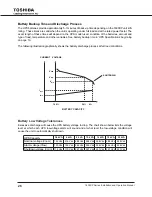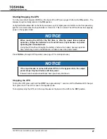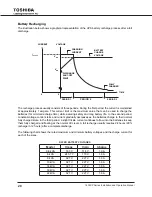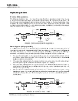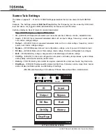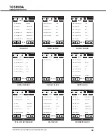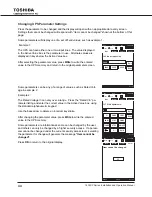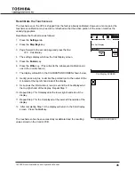
32
1600Xp Series installation and operation manual
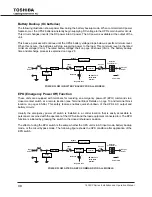
Display and Keys
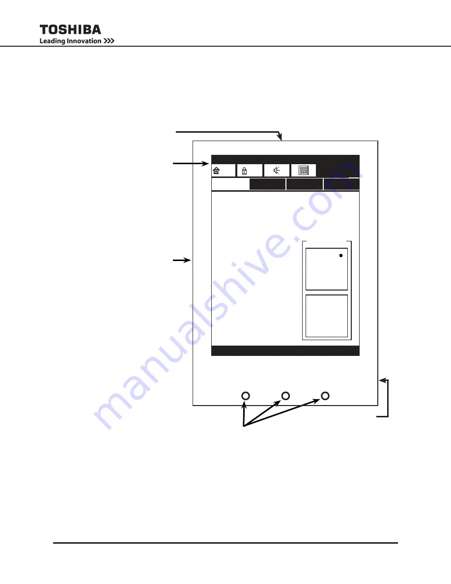
Front Panel Layout
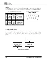
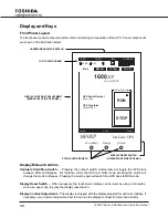
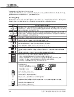
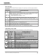
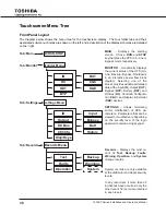
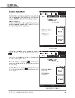
the front panel consists of several elements for monitoring and operation of the UpS. panel components
are shown in the illustration below:
Display Manual Controls
Hardware Start/Stop Switch –
pressing the contact switch momentarily will toggle the UpS state
between rUn and bypass. For instance, while the UpS is in rUn mode, pressing the switch will
change the mode to bypass. pressing the switch again will switch the UpS back to rUn mode.
Display Reset Switch –
when necessary, the touchscreen display can be reset by using a thin probe,
such as a paper clip, to press the display reset switch.
Display Contrast Adjustment –
the display is shipped with the display adjusted for optimum visibility. if
necessary use a trimmer adjustment tool to fine tune the display contrast for improved visibility.
DISPLAY CONTRAST ADjUSTMENT
(MIDDLE LEFT SIDE OF PANEL)
LCD TOUCH SCREEN
HARDWARE RUN/STOP SWITCH
STATUS LEDS (PAGE 35)
DISPLAY RESET SWITCH
(LOWER RIGHT SIDE OF PANEL)
On-Line/Fault
Warning
A/C Input
1600XP
On-Line UPS
Shutdown
ASyn
dVCoH
on-line
dVCoH
ASyn
1600
XP
On-Line UPS
UPS Serial Number
20080112345
UPS Typeform
UXpb2b100C6
RUN
STOP
UpS Controls
Main
Monitor
Settings
Records
12:35 pm
inV
HOME
USR
96%
100%

