47
1600XP/XPi Series Installation and Operation Manual – 60616-012
19.2 (Optional) External Maintenance Bypass
Wiring
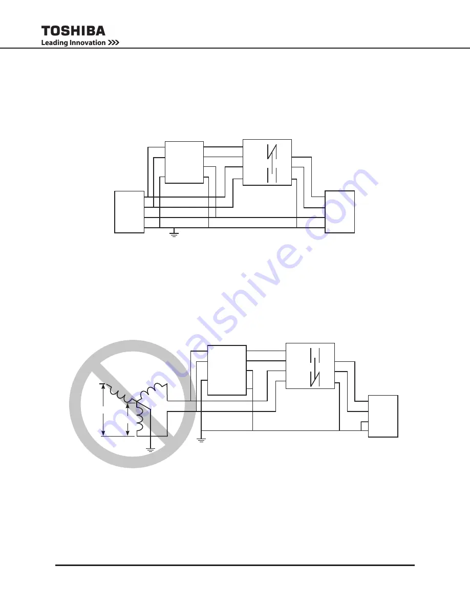
The following connections must be made to the Utility Panel and the Load Panel. The Main UPS output is
located on the terminal block on the back of the UPS. (TB-4(X1) and TB-7(X3) 240 VAC.)
See the application instructions included with the External Maintenance Bypass Unit for wiring details.
Do NOT use two legs of a three phase, 208/120V utility to feed the 1600XP/XPi, as shown below, if an
external maintenance bypass is being used. The phase shift between the output of the UPS and the util-
ity feed to the bypass could interrupt the power to to load.
DO NOT USE 3-PHASE INPUT WHEN USING AN EXTERNAL MAINTENANCE BYPASS
MAIN
OUTPUT
UTILITY
PANEL:
SINGLE
Φ
240V
L1
L2
N
G
LOAD
PANEL
L1
L2
N
G
UPS
L1
L2
G
X1
X3
N
G
MAINTENANCE
BYPASS
CBL1
CBL2
CBM1
CBM2
G
L1
L2
MAIN
OUTPUT
UTILITY
PANEL:
3
Φ
LOAD
PANEL
L1
L2
N
G
UPS
L1
L2
G
N
X1
X3
X2
120V
208V
X2
X3
G
X1
N
MAINTENANCE
BYPASS
CBL1
CBL2
CBM1
CBM2
G
L1
L2
Summary of Contents for 1600XP SERIES
Page 2: ...b 1600XP XPi Series Installation and Operation Manual 60616 012 ...
Page 6: ...f 1600XP XPi Series Installation and Operation Manual 60616 012 ...
Page 10: ...iv 1600XP XPi Series Installation and Operation Manual 60616 012 ...
Page 74: ...64 1600XP XPi Series Installation and Operation Manual 60616 012 ...
Page 112: ...B 32 1600XP XPi Series Installation and Operation Manual 60616 012 ...
Page 115: ...C3 1600XP XPi Series Installation and Operation Manual 60616 012 8 10 kVA Dimensions ...
Page 132: ...E2 1600XP XPi Series Installation and Operation Manual 60616 012 ...
Page 139: ......


