background image

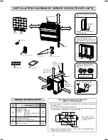
A

B

C

Toshiba 1112150201 (EN)

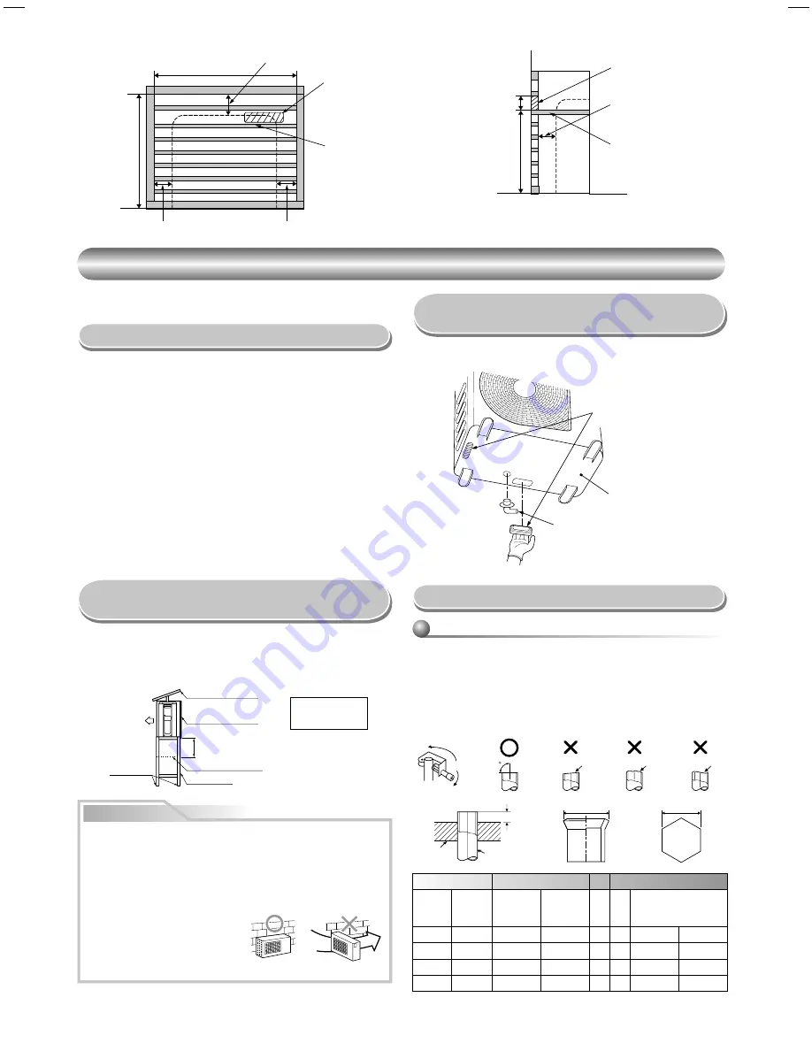
500

140

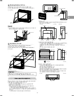
(Side view)

Partition board

20 to 30

Opening for receiver

(Front view)

800 or more

670 or more

Partition board

Opening for receiver

50 or more

50 or more

70 or more

OUTDOOR UNIT

OUTDOOR UNIT

Installation Place

  A place which provides enough spaces around the outdoor unit as shown 

in the diagram.

  A place which can bear the weight of the outdoor unit and does not allow 

an increase in noise level and vibration.

  A place where the operation noise and discharged air do not disturb your 

neighbors.

  A place which is not exposed to a strong wind.

  A place free of a leakage of combustible gases.

  A place which does not block a passage.

  When the outdoor unit is to be installed in an elevated position, be sure to 

secure its feet.

  This air conditioner accepts a connection piping length from 2 m to 20 m.


  There is no need to add refrigerant as long as the length of the  


  connection piping is 15 m or less. 


  You will need to add 20 g of refrigerant per meter of added connection   

  piping for installation requiring connection piping to be between 16 m to  
 20 

m. 

  An allowable height level is up to 10 m.

  A place where the drain water does not cause any problems.

CAUTION

1. Install the outdoor unit in a location where there are no obstructions 

near its air intake or air outlet.

2. When the outdoor unit is installed in a place that is always exposed to 

strong winds like on the coast or on a high story of a building, secure 
the normal fan operation using a duct or a wind shield.

3. Especially in windy areas, install the unit to prevent the admission of 

wind.

4. Installation in the following places may result in trouble. 
  Do not install the unit in such places.

  •

  A place full of machine oil.

  •

  A saline-place such as the coast.

  •

  A place full of sulfi de gas.

  •

  A place where high-frequency 

  waves are likely to be generated, 

    such as from audio equipment, welders, and medical equipment.

Strong

wind

Snow protection plate

Snow protection hood

At least 50 cm

Snow accumulation line

Holding frame

Front

Anchor bolts

Install at least 50 cm
above the snow
accumulation line.

  Do not use the supplied drain nipple for draining water. Drain the water from 

all the drain holes directly.

  To protect the outdoor unit from snow accumulation, install a holding frame, 

and attach a snow protection hood and plate.

*  Do not use a double-stacked design.

Precautions about Installation in Regions 

with Snowfall and Cold Temperatures

  When using a multi-system outdoor unit refer to the installation manual 

provided with the model concerned.

Refrigerant Piping Connection

Flaring

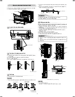
1. Cut the pipe with a pipe cutter.
2. Deburr the inside of the pipe at its end.
  Take steps to ensure that the removed burrs will not enter the pipe.
3. Remove the fl are nuts provided with the indoor and outdoor units, and 

insert them into the pipe.

4. Flare the pipe.
  The projection margin of the pipe must be checked.
5. Check that the fl are has the appropriate shape.

90

Obliquity

Roughness

Warp

Pipe

Die

  If it is necessary to drain off the water from the outdoor unit, install two 

water-proofi ng rubber caps and a drain nipple.

Draining off the Water 
from the Outdoor Unit

Pipe

A

B

Flare Nut

Outside

diameter

Thickness

Rigid 

(clutch type)

R410A tool

Imperial 

(wing nut 

type)

R410A tool

C

Tighten torque

mm

mm

mm

mm

mm

mm

N·m

kgf·m

6.35

0.8

0 to 0.5

1.5 to 2.0

9.1

17

14 to 18

1.4 to 1.8

9.52

0.8

0 to 0.5

1.5 to 2.0

13.2

22

33 to 42

3.3 to 4.2

12.7

0.8

0 to 0.5

2.0 to 2.5

16.6

26

50 to 62

5.0 to 6.2

Water-proof rubber caps
(supplied with the outdoor unit)

Drain nipple

Base plate

7

Summary of Contents for 18UFV-E1

Page 1: ...8SAV E RAS 3M26GAV E1 RAS 4M23SAV E RAS 4M27GAV E1 RAS 5M34UAV E AIR CONDITIONER SPLIT TYPE INSTALLATION MANUAL ENGLISH ESPAÑOL FRANÇAIS ITALIANO DEUTSCH PORTUGUÊS POLSKI ČESKY PУCСКИЙ HRVATSKI MAGYAR TÜRKÇE NEDERLANDS ΕΛΛΗΝΙΚΑ SVENSKA SUOMI NORSK DANSK ROMÂNĂ БЪЛГАРСКИ EESTI LATVISKI SLOVENČINA SLOVENŠČINA ...

Page 2: ...enie Instalacji Rurowej Czynnika Chłodniczego 7 n Usuwanie Powietrza 8 n Podłączenie Okablowania 8 n Prace Elektryczne 8 INNE 9 n Próba Gazoszczelności 9 n Ustawianie Przełącznika Wyboru Pilota 9 n Ustawienia Przełącznika A B Wyboru Pilota 9 n Próba Działania 9 n Włączanie Funkcji Automatycznego Wznawiania Pracy Auto Restart 9 PL OBSAH BEZPEČNOSTNÍ OPATŘENÍ 1 SCHÉMA INSTALACE VNITŘNÍ A VENKOVNÍ JE...

Page 3: ...talare Opţionale 3 UNITATE INTERIOARĂ 4 n Locul de Instalare 4 n Executarea unei Găuri şi Montarea Plăcii de Instalare 4 n Cum se Instalează Unitatea Interioară 5 n Instalarea Mascată 6 UNITATEA EXTERIOARĂ 7 n Locul de Instalare 7 n Măsuri de Precauţie privind Instalarea în Regiuni cu ninsori Abundente şi Temperaturi Scăzute 7 n Drenarea Apei din Unitatea Exterioară 7 n Racordarea Ţevilor de lichi...

Page 4: ...s of charging port connecting sections on the main unit are different from those for the conventional refrigerant and different size tools are also required For connecting pipes use new and clean piping materials with highpressure withstand capabilities designed for R410A only and ensure that water or dust does not enter Moreover do not use any existing piping as its pressure withstand may be insu...

Page 5: ...t enough or installation of the unit is improper the unit may fall and result in injury Electrical work must be performed by a qualified electrical engineer in accordance with the code governing such installation work internal wiring regulations and the manual A dedicated circuit and the rated voltage must be used Insufficient power supply or improper installation may cause electrical shock or fir...

Page 6: ...If it is necessary to drain the defrost water attach drain nipple and cap water proof to the bottom plate of the outdoor unit before installing it Fixing bolt arrangement of outdoor unit RAS 10 13 18SAV Series 3 Batteries 8 Pan head wood screw 4 Remote control holder Do not allow the drain hose to get slack Make sure to run the drain hose sloped downward The auxiliary piping can be connected to th...

Page 7: ...hole brim ring sold separately A place which provides the spaces around the indoor unit as shown in the diagram A place where there are no obstacles near the air inlet and outlet A place which allows easy installation of the piping to the outdoor unit A place which allows the front panel to be opened In case of block brick concrete or similar type walls make 5 mm holes in the wall Insert clip anch...

Page 8: ... Do not form the drain hose into a wavy shape Do not put the drain hose end into water Do not put the drain hose end in the drainage ditch Drainage 1 Run the drain hose sloped downwards Wiring connection Wiring of the connection cable is necessary to remove the front panel 1 Remove the terminal cover and cord clamp 2 Insert the connecting cable according to the local rule into the pipe hole on the...

Page 9: ...or more 20 to 30 240 to 250 Floor Wall Side view Unit mm 4 In case of lattice establishment Follow the following figure make sure to keep enough distance between lattice frame and wall Be sure to switch to wall burying mode The lattice should be make of wood Between the air inlet and outlet should be devided with partition board Be sure to establish the open part for RECEIVER The open part of latt...

Page 10: ...A place full of machine oil A saline place such as the coast A place full of sulfide gas A place where high frequency waves are likely to be generated such as from audio equipment welders and medical equipment Strong wind Snow protection plate Snow protection hood At least 50 cm Snow accumulation line Holding frame Front Anchor bolts Install at least 50 cm above the snow accumulation line Do not u...

Page 11: ...en fully the valve stem of the packed valves both gas and liquid sides 7 Remove the charging hose from the service port 8 Securely tighten the caps on the packed valves VACUUMING Evacuate the air in the connecting pipes and in the indoor unit using a vacuum pump Do not use the refrigerant in the outdoor unit For details see the manual of the vacuum pump Tightening torque for connection of flare pi...

Page 12: ...ote Control by the tip of the pencil 00 will be shown on the display 2 Press during pushing B will show on the display and 00 will disappear and the air conditioner will turn OFF The Remote Control B is memorized Note 1 Repeat above step to reset Remote Control to be A 2 Remote Control A has not A display 3 Default setting of Remote Control from factory is A Unit B setup Press and hold MODE button...

Page 13: ...1112150201 1 ...
Reviews: