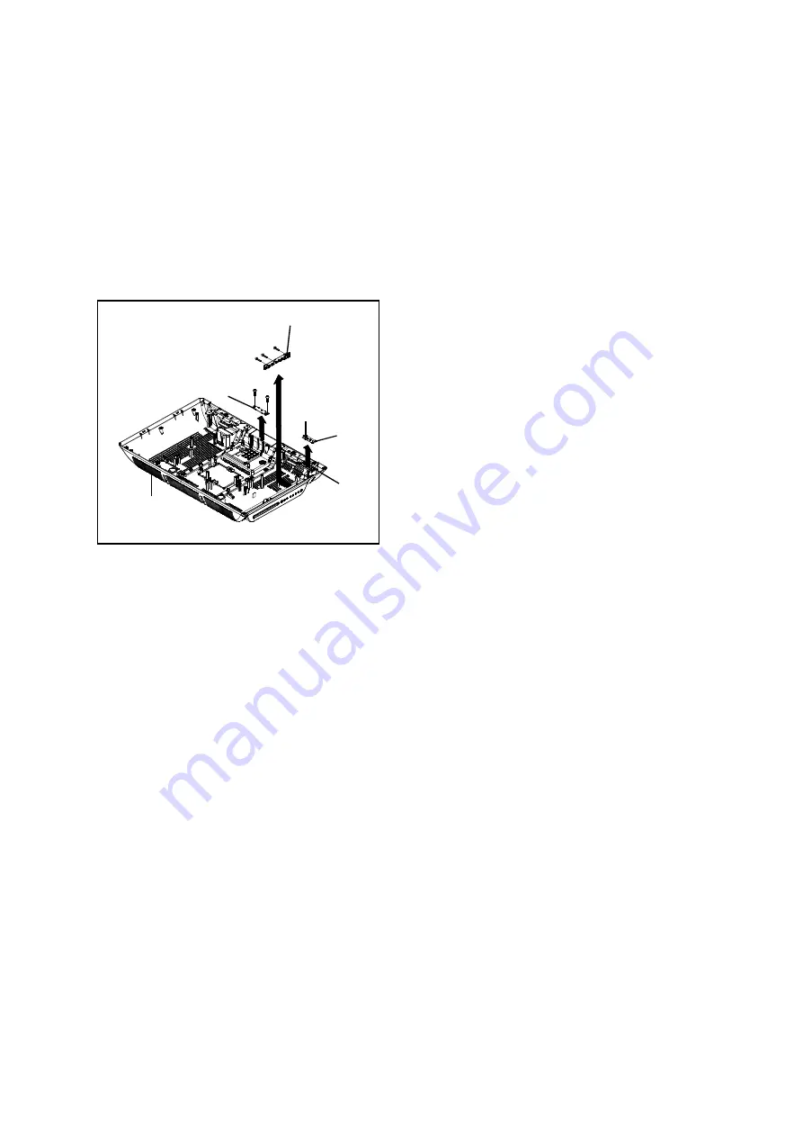
1-8: REMOCON PCB, LED PCB and OPERATION PCB
(Refer to Fig. 1-8)
1. Disconnect the following connectors :
(CP2201)
.
2. Unlock the support (1).
3. Remove the Remocon PCB in the direction of arrow (A).
4. Remove the 2 screws (2).
5. Remove the LED PCB in the direction of arrow (B).
6. Remove the 3 screws (3).
7. Remove the Operation PCB in the direction of arrow (C).
DISASSEMBLY INSTRUCTIONS
(A)
(3)
(2)
(C)
(B)
Back Cabinet Ass'y
(3)
Remocon PCB
Operation PCB
(3)
LED PCB
(1)
(2)
CP2201
B1-9
26LV610U
Fig. 1-8
B1-9
26LV610U


