background image

4

INDOOR UNIT

INDOOR UNIT

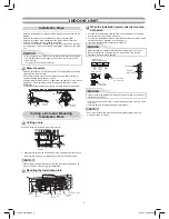
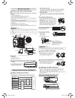
Installation Place

•  Direct sunlight to the indoor unit’s wireless receiver should be avoided.
•  The microprocessor in the indoor unit should not be too close to RF 

noise sources.

  (For details, see the owner’s manual.)  


Remote control

•  A place where there are no obstacles such as a curtain that may block the 

signal from the remote control.

•  Do not install the remote control in a place exposed to direct sunlight or 

close to a heating source such as a stove.

•  Keep the remote control at least 1 m apart from the nearest TV set or stereo 

equipment. (This is necessary to prevent image disturbances or noise 
interference.)

•  The location of the remote control should be determined as shown below.

Cutting a Hole and Mounting

Installation Plate


NOTE

•  When drilling a wall that contains a metal lath, wire lath or metal plate, be 

sure to use a pipe hole brim ring sold separately.


Cutting a hole

When installing the refrigerant pipes from the rear


Mounting the installation plate

When the installation plate is directly mounted 
on the wall

1. Securely 

fi

 t the installation plate onto the wall by screwing it in the upper 

and lower parts to hook up the indoor unit.

2.  To mount the installation plate on a concrete wall with anchor bolts, use the 

anchor bolt holes as illustrated in the below 

fi

 gure.

3.  Install the installation plate horizontally in the wall.

When installing the installation plate with a mounting screw, do not use 
the anchor bolt holes. Otherwise, the unit may fall down and result in 
personal injury and property damage.  

1.  After determining the pipe hole position on the mounting plate (

), drill the 

pipe hole (dia. 65 mm) at a slight downward slant to the outdoor side. 

•  A place which provides the spaces around the indoor unit as shown in the 

diagram

•  A place where there are no obstacles near the air inlet and outlet
•  A place which allows easy installation of the piping to the outdoor unit
•  A place which allows the front panel to be opened
•  The indoor unit shall be installed as top of the indoor unit comes to at least 

2 m height. Also, it must be avoided to put anything on the top of the indoor 
unit.  

CAUTION

m from the right side edge is

e

 center of pipe hole

35

120

180

240

The center of the pipe hole is above 
the arrow.

Pipe hole

CAUTION

Failure to 

fi

 rmly install the unit may result in personal injury and property 

damage if the unit falls.

•  In case of block, brick, concrete or similar type walls, make 5 mm dia. holes 

in the wall.

•  Insert clip anchors for appropriate mounting screws 

7

.


NOTE

•  Secure four corners and lower parts of the installation plate with 4 to 6 

mounting screws to install it.

7

CAUTION

To unit out line 

240mm

To unit out line 

35mm

To unit out line 

240mm

Offset 23mm from the right side edge is

the center of pipe hole

To unit out line 

120mm

0

23

35

120

180

240

Offset 85mm from the left side edge is

the center of pipe hole

170

170

50

40

85

132

23

1

7

Anchor bolt holes

Hook

Hook

Hook

Pipe hole

Pipe hole (dia. 65mm)

Installation
plate

Weight

Indoor unit

Thread

2 m or more from 

fl

 oor

Mounting 
Screw

23mm

dia. 65mm

Installation plate
(Keep horizontal direction.)

5 mm dia. hole

Mounting screw
dia. 4 mm x 25

R

Clip anchor
(local parts)

Anchor boltt

Projection
15 mm or less

dia. 

65mm


5

4

°

45

°

5

7

°

(Side view)

(Top view)

Indoor unit

Reception range

Remote 
control

Remote
control

Reception
range

Indoor unit

1110651154-EN.indd   4

1110651154-EN.indd   4

2/15/10   9:39:38 AM

2/15/10   9:39:38 AM

Summary of Contents for 22SAV

Page 1: ...r unit RAS 18 22SKV R Series Outdoor unit RAS 18 22SAV Series AIR CONDITIONER SPLIT TYPE INSTALLATION MANUAL 1110651154 Cover 1110651154 indd 1 Cover 1110651154 indd 1 1 22 10 11 14 26 AM 1 22 10 11 14 26 AM ...

Page 2: ...Installation 5 n Indoor Unit Fixing 6 n Drainage 6 OUTDOOR UNIT 6 n Installation Place 6 n Precautions about Installation in Regions with Snowfall and Cold Temperatures 6 n Refrigerant Piping Connection 7 n Evacuating 7 n Wiring Connection 7 n Electrical Work 7 OTHERS 8 n Gas Leak Test 8 n Remote Control A B Selection 8 n Test Operation 8 n Auto Restart Setting 8 Cover 1110651154 indd 2 Cover 1110...

Page 3: ...ing in damage to the unit or injury Do not modify the power cable connect the cable midway or use a multiple outlet extension cable Doing so may cause contact failure insulation failure or excess current resulting in fire or electrical shock If you detect any damage do not install the unit Contact your supplying dealer immediately New refrigerant air conditioner installation CAUTION THIS AIR CONDI...

Page 4: ...use electrical shock Follow the instructions in this installation manual to arrange the drain pipe for proper drainage from the unit Ensure that drained water is discharged Improper drainage can result in water leakage causing water damage to furniture Tighten the flare nut with a torque wrench using the prescribed method Do not apply excess torque Otherwise the nut may crack after a long period o...

Page 5: ...rain hose to get slack Cut the piping hole sloped slightly The auxiliary piping can be connected to the left rear left rear right right bottom right or bottom left Right Rear right Bottom right Rear left Bottom left Left 8 mm thick heat resisting polyethylene foam 1 Batteries Pan head wood screw Remote control holder Vinyl tape Apply after carrying out a drainage test Wireless remote control Saddl...

Page 6: ...he pipe hole dia 65 mm at a slight downward slant to the outdoor side A place which provides the spaces around the indoor unit as shown in the diagram A place where there are no obstacles near the air inlet and outlet A place which allows easy installation of the piping to the outdoor unit A place which allows the front panel to be opened The indoor unit shall be installed as top of the indoor uni...

Page 7: ...pipe make sure to use a spring bender so as not to crush the pipe Bend the connecting pipe within a radius of 30 mm To connect the pipe after installation of the unit figure How to install the air inlet grille on the indoor unit When attaching the air inlet grille perform the same process as for removal but in reverse order Wiring Connection Wiring of the connecting cable can be carried out withou...

Page 8: ...cause any problems CAUTION 1 Install the outdoor unit in a location where there are no obstructions near its air intake or air outlet 2 When the outdoor unit is installed in a place that is always exposed to strong winds like on the coast or on a high story of a building secure the normal fan operation using a duct or a wind shield 3 Especially in windy areas install the unit to prevent the admiss...

Page 9: ...uid side Service port Valve core Setting pin Packed valve at gas side Vacuum pump Vacuum pump adapter for counter flow prevention For R410A only Charge hose For R410A only Handle Hi Keep full closed Manifold valve Pressure gauge Compound pressure gauge Handle Lo Charge hose For R410A only Connecting pipe 101 kPa 76 cmHg Open the valve stem until it touches the stopper Once it is in contact with th...

Page 10: ...ns for the gas leak with a gas leak detector or soap water This product is designed so that after a power failure it can restart automatically in the same operating mode as before the power failure 1 Press and hold the RESET button on the indoor unit for 3 seconds to set the operation 3 beep sound and OPERATION lamp blink 5 time sec for 5 seconds 2 Press and hold the RESET button on the indoor uni...

Page 11: ...Cover back 1110651154 indd 1 Cover back 1110651154 indd 1 1 22 10 11 15 21 AM 1 22 10 11 15 21 AM ...

Page 12: ...Cover back 1110651154 indd 2 Cover back 1110651154 indd 2 1 22 10 11 15 22 AM 1 22 10 11 15 22 AM ...

Reviews: