Nov. 1997 © TOSHIBA
5 - 1
3560/70 DISPLAY
5.
DISPLAY UNIT
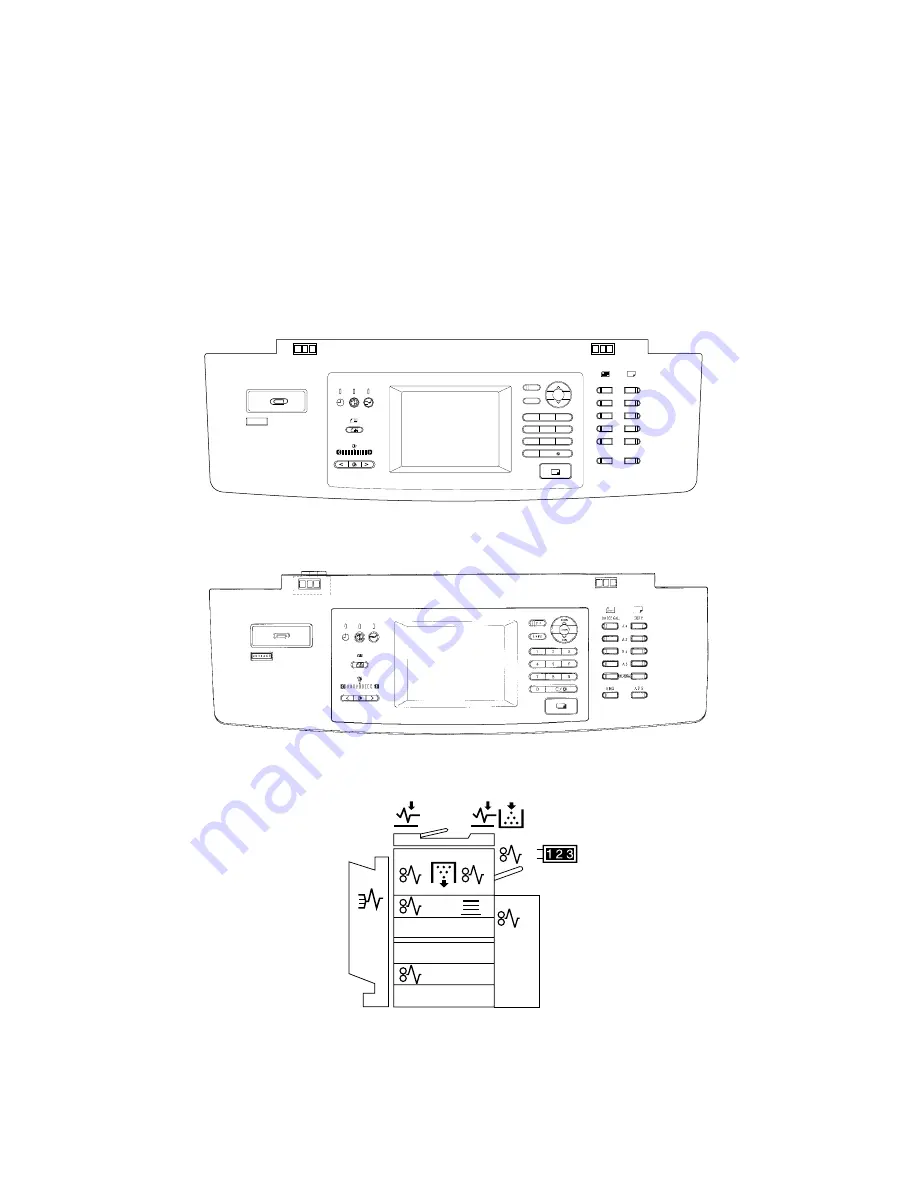
The display unit consists of key switches for copier operation/selection of each mode, LEDs and an LCD
displaying the copier state or messages.
Particularly, when the operator’s attention is recommended, a graphic symbol lights or flashes and the
message indicating that condition is displayed.
5.1
Detailed Drawing of the Control Panel and the Display Panel
For the U.S.A. and Canada
LD
ORIGINAL
ZOOM
COPYSIZE
LG
LT
ST
OTHER
TIMER ENERGYSAVER
IMAGEMODE
LIGHT AUTO DARK
FUNCTION CLEAR
CLEAR/STOP
AMS
APS
INTERRUPT
200%
100%
50%
FC
HELP
1
2
3
4
5
6
7
8
9
0
C /
Details of the display panel
For Europe
Arrangement of the control panel
Summary of Contents for 3560
Page 21: ...3560 70 GENERAL 2 14 Nov 1997 TOSHIBA B Location diagram for lower unit ...
Page 72: ...Nov 1997 TOSHIBA 13 25 3560 70 CIRCUIT DIAGRAMS 13 3 Power Supply Circuit PS ACC A 115 V ...
Page 73: ...3560 70 CIRCUIT DIAGRAMS 13 26 Nov 1997 TOSHIBA B 230 V ...
Page 77: ...Nov 1997 TOSHIBA 15 1 3560 70 PC BOARD 15 PC BOARD ASSEMBLY 15 1 PWA LGC ...
Page 78: ...3560 70 PC BOARD 15 2 Nov 1997 TOSHIBA 15 2 PWA PNL ...
Page 79: ...Nov 1997 TOSHIBA 15 3 3560 70 PC BOARD 15 3 PWA KEY KEY1 KEY2 ...
Page 80: ...3560 70 PC BOARD 15 4 Nov 1997 TOSHIBA 15 4 PWA ERS ...
Page 81: ...Nov 1997 TOSHIBA 15 5 3560 70 PC BOARD 15 5 PS ACC A 1 115V ...
Page 82: ...3560 70 PC BOARD 15 6 Nov 1997 TOSHIBA A 2 230V ...


