3560/70 CLEANER
11 - 2
Nov. 1997 © TOSHIBA
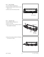
11.4.3
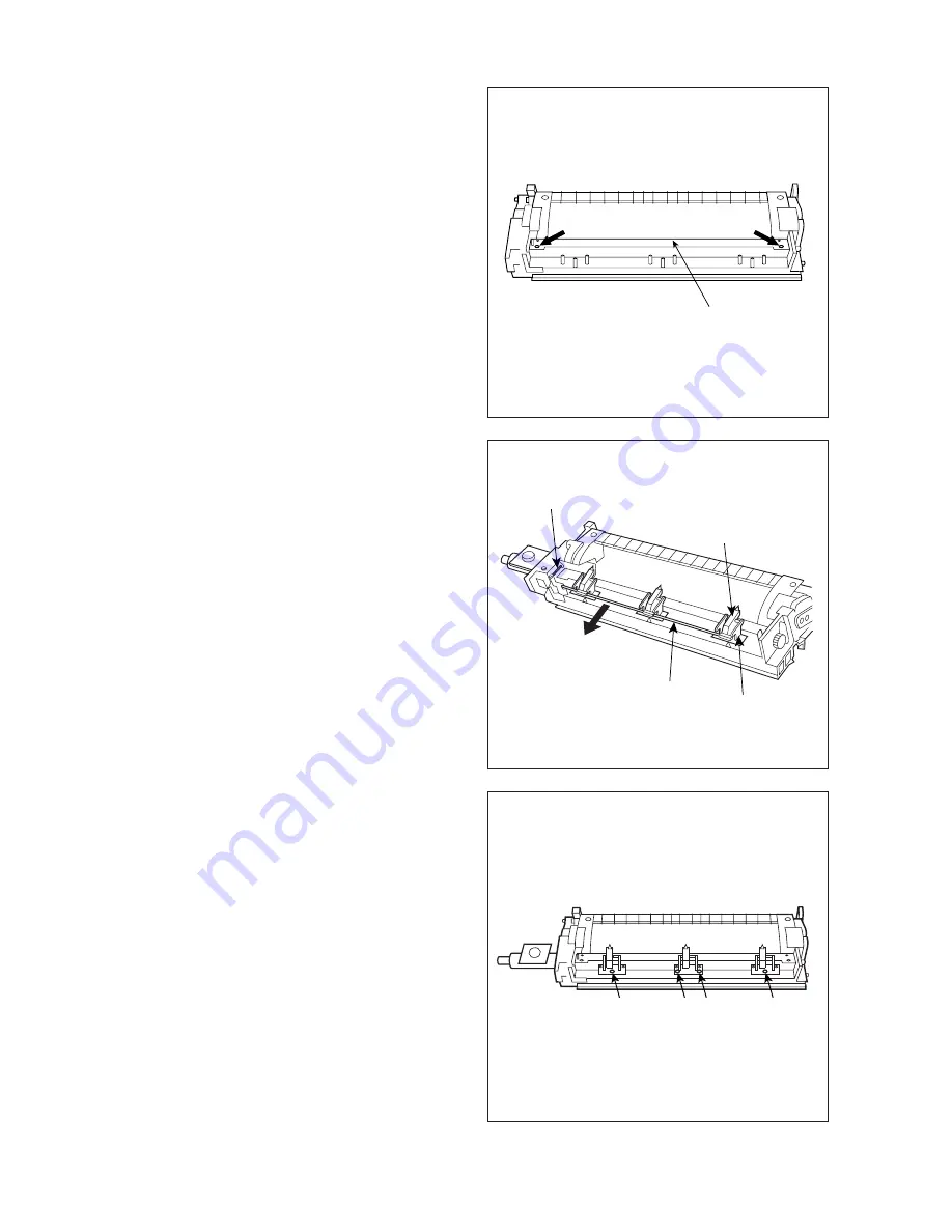
Recovery blade
(1) Turn the cleaner unit upside down.
(2) Remove the three separation claws (4 screws).
Refer to 11.4.4.
(3) Remove the recovery blade (2 screws).
11.4.4
Separation claw
(1) Turn the cleaner unit upside down.
(2) Remove the spring.
(3) Remove the lever from the fitting sections of
the separation claw holders.
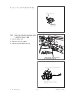
(4) Remove the 4 screws and take out the separa-
tion claw with the holder.
Recovery blade
Spring
Separation claw
Separation
claw holder
Lever
Summary of Contents for 3560
Page 21: ...3560 70 GENERAL 2 14 Nov 1997 TOSHIBA B Location diagram for lower unit ...
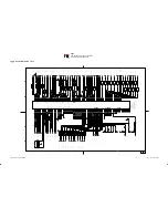
Page 72: ...Nov 1997 TOSHIBA 13 25 3560 70 CIRCUIT DIAGRAMS 13 3 Power Supply Circuit PS ACC A 115 V ...
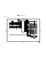
Page 73: ...3560 70 CIRCUIT DIAGRAMS 13 26 Nov 1997 TOSHIBA B 230 V ...
Page 77: ...Nov 1997 TOSHIBA 15 1 3560 70 PC BOARD 15 PC BOARD ASSEMBLY 15 1 PWA LGC ...
Page 78: ...3560 70 PC BOARD 15 2 Nov 1997 TOSHIBA 15 2 PWA PNL ...
Page 79: ...Nov 1997 TOSHIBA 15 3 3560 70 PC BOARD 15 3 PWA KEY KEY1 KEY2 ...
Page 80: ...3560 70 PC BOARD 15 4 Nov 1997 TOSHIBA 15 4 PWA ERS ...
Page 81: ...Nov 1997 TOSHIBA 15 5 3560 70 PC BOARD 15 5 PS ACC A 1 115V ...
Page 82: ...3560 70 PC BOARD 15 6 Nov 1997 TOSHIBA A 2 230V ...


