Nov. 1997 © TOSHIBA
17 - 5
3560/70 INSTALLATION
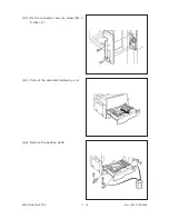
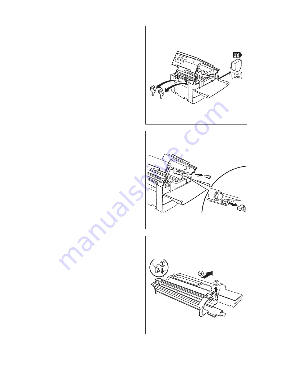
(13) Remove the pressure release bracket (2
pcs.) from the fuser unit.
.
Remove the toner cartridge (only for
AUD, TWD, SAD, ASD).
(15) Place the process unit on a flat surface.
Raise the lever located on each side of the
process unit in the direction of the arrow.
.
Remove the developer unit from the
process unit.
Note: If the photoconductor is exposed to fluo-
rescent light or external light for long
time, it may suffer from light-caused
fatigue. So, be sure to cover the process
unit with, for example, a suitable cloth.
(14) Remove the screw (1) and connector (1),
then the process unit.
Summary of Contents for 3560
Page 21: ...3560 70 GENERAL 2 14 Nov 1997 TOSHIBA B Location diagram for lower unit ...
Page 72: ...Nov 1997 TOSHIBA 13 25 3560 70 CIRCUIT DIAGRAMS 13 3 Power Supply Circuit PS ACC A 115 V ...
Page 73: ...3560 70 CIRCUIT DIAGRAMS 13 26 Nov 1997 TOSHIBA B 230 V ...
Page 77: ...Nov 1997 TOSHIBA 15 1 3560 70 PC BOARD 15 PC BOARD ASSEMBLY 15 1 PWA LGC ...
Page 78: ...3560 70 PC BOARD 15 2 Nov 1997 TOSHIBA 15 2 PWA PNL ...
Page 79: ...Nov 1997 TOSHIBA 15 3 3560 70 PC BOARD 15 3 PWA KEY KEY1 KEY2 ...
Page 80: ...3560 70 PC BOARD 15 4 Nov 1997 TOSHIBA 15 4 PWA ERS ...
Page 81: ...Nov 1997 TOSHIBA 15 5 3560 70 PC BOARD 15 5 PS ACC A 1 115V ...
Page 82: ...3560 70 PC BOARD 15 6 Nov 1997 TOSHIBA A 2 230V ...


