3560/70 INSTALLATION
17 - 6
Nov. 1997 © TOSHIBA
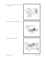
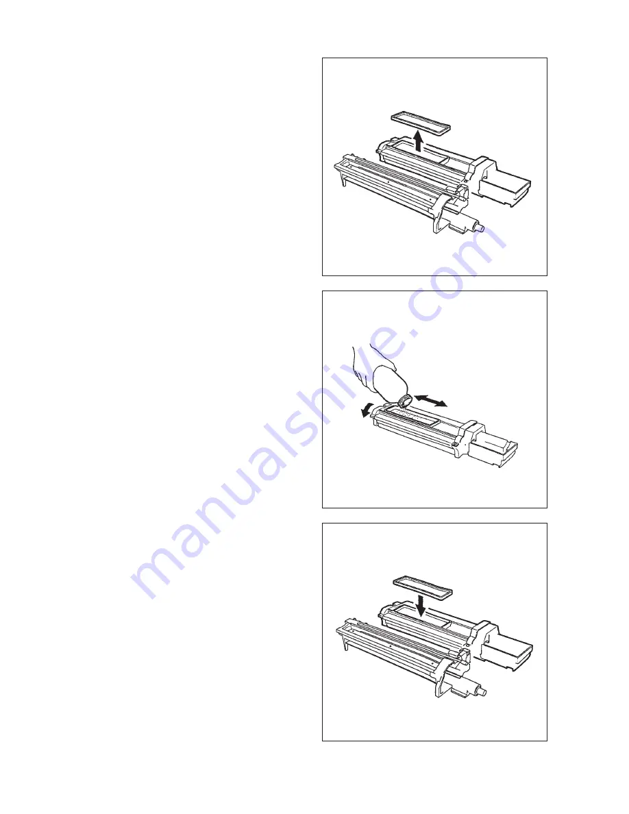
(16) Remove the top cover of the developer unit.
(18) Reinstall the top cover.
Be sure to install the top cover firmly.
(17) Pour in the developer material.
Note: Before pouring in the developer material,
be sure to shake the developer bottle
fully.
By rotating the magnetic roller, check to
make sure that the developer material is
transported properly.
Summary of Contents for 3560
Page 21: ...3560 70 GENERAL 2 14 Nov 1997 TOSHIBA B Location diagram for lower unit ...
Page 72: ...Nov 1997 TOSHIBA 13 25 3560 70 CIRCUIT DIAGRAMS 13 3 Power Supply Circuit PS ACC A 115 V ...
Page 73: ...3560 70 CIRCUIT DIAGRAMS 13 26 Nov 1997 TOSHIBA B 230 V ...
Page 77: ...Nov 1997 TOSHIBA 15 1 3560 70 PC BOARD 15 PC BOARD ASSEMBLY 15 1 PWA LGC ...
Page 78: ...3560 70 PC BOARD 15 2 Nov 1997 TOSHIBA 15 2 PWA PNL ...
Page 79: ...Nov 1997 TOSHIBA 15 3 3560 70 PC BOARD 15 3 PWA KEY KEY1 KEY2 ...
Page 80: ...3560 70 PC BOARD 15 4 Nov 1997 TOSHIBA 15 4 PWA ERS ...
Page 81: ...Nov 1997 TOSHIBA 15 5 3560 70 PC BOARD 15 5 PS ACC A 1 115V ...
Page 82: ...3560 70 PC BOARD 15 6 Nov 1997 TOSHIBA A 2 230V ...


