background image

CAUTION

  Please read this installation manual carefully before installing the unit. It contains further important instructions for proper installation. 

  Exposure of unit to water or other moisture before installation could result in electric shock. Do not store it in a wet basement or expose to rain or water.

  After unpacking the unit, examine it carefully for possible damage.

  Do not install in a place that can increase the vibration of the unit. Do not install in a place that can amplify the noise level of the unit or where noise and 

discharged air might disturb neighbors.

  This appliance must be connected to the main power supply by means of a circuit breaker depending on the place where the unit is installed. Failure to 

do so may cause electrical shock.

  Follow the instructions in this installation manual to arrange the drain pipe for proper drainage from the unit. Ensure that drained water is discharged.

Improper drainage can result in water leakage, causing water damage to furniture.

  Tighten the fl are nut with a torque wrench using the prescribed method. Do not apply excess torque. Otherwise, the nut may crack after a long period of 

usage and it may cause the leakage of refrigerant.

  Wear gloves (heavy gloves such as cotton gloves) for installation work. Failure to do so may cause personal injury when handling parts with sharp 

edges.

  Do not touch the air intake section or the aluminum fi ns of the outdoor unit. It may cause injury.

  Do not install the outdoor unit in a place which can be a nest for small animals. Small animals could enter and contact internal electrical parts, causing a 

failure or fi re.

  Request the user to keep the place around the unit tidy and clean.

  Make sure to conduct a trial operation after the installation work, and explain how to use and maintain the unit to the customer in accordance with the 

manual. Ask the customer to keep the operation manual along with the installation manual.

REQUIREMENT OF REPORT TO THE LOCAL POWER SUPPLIER

Please make absolutely sure that the installation of this appliance is reported to the local power supplier before installation. If you experience any problems 
or if the installation is not accepted by the supplier, the service agency will take adequate countermeasures.

WARNING

  Installation work must be requested from the supplying retail dealership or professional vendors. Self-installation may cause water leakage, electrical 

shock, or fi re as a result of improper installation.

  Specifi ed tools and pipe parts for model R410A are required, and installation work must be done in accordance with the manual. HFC type refrigerant 

R410A has 1.6 times more pressure than that of conventional refrigerant (R22). Use the specifi ed pipe parts, and ensure correct installation, otherwise 
damage and/or injury may be caused. At the same time, water leakage, electrical shock, and fi re may occur.

  Be sure to install the unit in a place which can suffi ciently bear its weight. If the load bearing of the unit is not enough, or installation of the unit is 

improper, the unit may fall and result in injury.

  Electrical work must be performed by a qualifi ed electrical engineer in accordance with the code governing such installation work, internal wiring 

regulations, and the manual. A dedicated circuit and the rated voltage must be used. Insuffi cient power supply or improper installation may cause 
electrical shock or fi re.

  Use a cabtyre cable to connect wires in the indoor/outdoor units. Midway connection, stranded wire, and single-wire connections are not allowed.

Improper connection or fi xing may cause a fi re.

  Wiring between the indoor unit and outdoor units must be well shaped so that the cover can be fi rmly placed. Improper cover installation may cause 

increased heat, fi re, or electrical shock at the terminal area.

  Be sure to use only approved accessories or the specifi ed parts. Failure to do so may cause the unit to fall, water leakage, fi re or electrical shock.

  After the installation work, ensure that there is no leakage of refrigerant gas. If the refrigerant gas leaks out of the pipe into the room and is heated by 

fi re or something else from a fanheater, stove or gas range, it causes generation of poisonous gas.

  Make sure the equipment is properly earthed. Do not connect the earth wire to a gas pipe, water pipe, lightning conductor, or telephone earth wire.

Improper earth work may be the cause of electrical shock.

  Do not install the unit where fl ammable gas may leak. If there is any gas leakage or accumulation around the unit, it can cause a fi re.

  Do not select a location for installation where there may be excessive water or humidity, such as a bathroom. Deterioration of insulation may cause 

electrical shock or fi re.

  Installation work must be performed following the instructions in this installation manual. Improper installation may cause water leakage, electrical shock 

or fi re. Check the following items before operating the unit.

  - Be sure that the pipe connection is well placed and there are no leaks.
  - Check that the service valve is open. If the service valve is closed, it may cause overpressure and result in compressor damage. At the same time, if

  there is a leak in the connection part, it may cause air suction and overpressure, resulting burst or injury.

  In pump down operations, ensure to perform the following procedures.

  - Do not inject air into the refrigeration cycle.
  - Be sure to close both service valves and stop the compressor before removing the refrigerant pipe. If removing the refrigerant pipe while the  


  compressor is operating with the service valves opened, it may cause to air absorbed and abnormal high pressure inside the refrigeration cycle and  
  resulting burst or injury.

  Do not modify the power cable, connect the cable midway, or use a multiple outlet extension cable. Doing so may cause contact failure, insulation 

failure, or excess current, resulting in fi re or electrical shock.

  If you detect any damage, do not install the unit. Contact your supplying dealer immediately. 

  Never modify this unit by removing any of the safety guards or bypassing any of the safety interlock switches.

2

Summary of Contents for 35S3AVP-ND

Page 1: ...1112150205 Indoor unit RAS 25 35UFV ND Outdoor unit RAS 25 35S3AVP ND AIR CONDITIONER SPLIT TYPE INSTALLATION MANUAL ENGLISH SVENSKA SUOMI NORSK ...

Page 2: ...aimen Valitsinkytkimen Säätäminen 9 Kauko ohjaimen A B Valinta 9 Koekäyttö 9 Automaattisen Uudelleenkäynnistyksen Asettaminen 9 FI INNHOLD SIKKERHETSREGLER 1 KOBLINGSSKJEMA FOR INNE OG UTENDØRSENHETEN 3 Ekstrautstyr 3 INNENHETEN 4 Plassering 4 Lage et Hull og Montere Montasjeplaten 4 Slik Monterer du Innendørsenheten 5 Skjult Montering 6 UTENDØRSENHET 7 Montasjested 7 Forholdsregler ved Installasj...

Page 3: ...harging port connecting sections on the main unit are different from those for the conventional refrigerant and different size tools are also required For connecting pipes use new and clean piping materials with highpressure withstand capabilities designed for R410A only and ensure that water or dust does not enter Moreover do not use any existing piping as its pressure withstand may be insufficie...

Page 4: ...f the load bearing of the unit is not enough or installation of the unit is improper the unit may fall and result in injury Electrical work must be performed by a qualified electrical engineer in accordance with the code governing such installation work internal wiring regulations and the manual A dedicated circuit and the rated voltage must be used Insufficient power supply or improper installati...

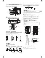
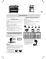
Page 5: ... ND 3 Batteries 6 Flat head wood screw 4 Remote control holder Remark Detail of accessory and installation parts can see in the accessory sheet When installing the outdoor unit leave open in at least two of direction A B C and D shown in the figure on the right Do not allow the drain hose to get slack Make sure to run the drain hose sloped downward The auxiliary piping can be connected to the left...

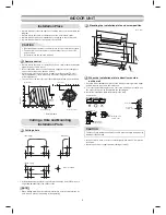
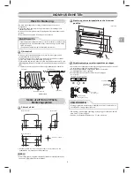
Page 6: ...r metal plate be sure to use a pipe hole brim ring sold separately A place which provides the spaces around the indoor unit as shown in the diagram A place where there are no obstacles near the air inlet and outlet A place which allows easy installation of the piping to the outdoor unit A place which allows the front panel to be opened In case of block brick concrete or similar type walls make 5 m...

Page 7: ...t form the drain hose into a wavy shape Do not put the drain hose end into water Do not put the drain hose end in the drainage ditch Drainage 1 Run the drain hose sloped downwards Wiring connection Wiring of the connection cable is necessary to remove the front panel 1 Remove the terminal cover and cord clamp 2 Insert the connecting cable according to the local rule into the pipe hole on the wall ...

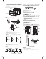
Page 8: ... Front view 70 or more 800 or more Wall Floor 670 or more 20 to 30 240 to 250 Floor Wall Side view Unit mm 4 In case of lattice establishment Follow the following figure make sure to keep enough distance between lattice frame and wall Be sure to switch to wall burying mode The lattice should be make of wood Between the air inlet and outlet should be devided with partition board Be sure to establis...

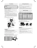
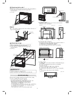
Page 9: ...frequency waves are likely to be generated such as from audio equipment welders and medical equipment Strong wind Snow protection plate Snow protection hood At least 50 cm Snow accumulation line Holding frame Front Anchor bolts Install at least 50 cm above the snow accumulation line Do not use the supplied drain nipple for draining water Drain the water from all the drain holes directly To protect...

Page 10: ... the piping length is 20 meters 15 minutes for 20 meters assuming a pump capacity of 27 liters per minute Then confirm that the compound pressure gauge reading is 101 kPa 76 cmHg 5 Close the low pressure side valve handle of the gauge manifold valve 6 Open fully the valve stem of the packed valves both gas and liquid sides 7 Remove the charging hose from the service port 8 Securely tighten the cap...

Page 11: ... 00 will be shown on the display 2 Press during pushing B will show on the display and 00 will disappear and the air conditioner will turn OFF The Remote Control B is memorized Note 1 Repeat above step to reset Remote Control to be A 2 Remote Control A has not A display 3 Default setting of Remote Control from factory is A Unit B setup Press and hold MODE button for more than 20 seconds When A set...

Page 12: ...kylolja blandas så är huvudenhetens påfyllningsportar och anslutningsdelar av en annan storlek än de för konventionellt köldmedium och det krävs också verktyg av andra storlekar Till förbindelserör ska endast nya och rena rörledningar som enbart är avsedda för R410A och tål högt tryck användas Se till att vatten eller damm inte kommer in i ledningarna Befintliga rörledningar kan vara förorenade oc...

Page 13: ...n enheten falla och förorsaka allvarlig skada Elektriskt arbete måste utföras av en behörig elektriker på det sätt som krävs för sådant installationsarbete och föreskrivs i lokala elkopplingsregler och i handboken En särskild strömkrets och rätt märkspänning måste användas För svag ström eller felaktig installation kan ge elstötar eller förorsaka brand Använd en cabtyre kabel för anslutning av led...

Page 14: ...eten ska minst två av riktningarna A B C och D lämnas öppna Se figuren till höger Låt inte dräneringsslangen slakna Se till att montera dräneringsslangen så att den lutar nedåt Hjälpröret kan anslutas till vänster baktill på vänster eller höger sida till höger eller nedtill till vänster eller höger sida Köldmedierören ska isoleras separat och inte tillsammans Värmeresistent polyetenskum 8 mm tjock...

Page 15: ...ng inomhusenheten som visas i diagrammet Det får inte finnas några blockeringar eller hinder för luftintaget eller utblåset på platsen Det ska vara enkelt att montera rörledningarna till utomhusenheten från platsen Det måste finnas utrymme för att öppna frontpanelen Vid montage på blockvägg tegelvägg betongvägg eller liknande ska hål med 5 mm göras i väggen Ankaren för passande fästskruvar nr 5 sk...

Page 16: ...angen får inte ha någon uppåtlutande del Dräneringsslangen får inte vågformas Dräneringsslangens ände får inte stoppas ned i vatten Dräneringsslangens ände får inte stoppas ned i dräneringsränna eller dike Dränering 1 Se till att dräneringsslangen har nedåtlutning Ledningsdragningar Dragning av anslutningskabel krävs för att kunna ta bort frontpanelen 1 Ta bort kabelklämman och skyddet för plintbl...

Page 17: ...husenhet 50 eller mer Framifrån 70 eller mer 800 eller mer Vägg Våning 670 eller mer 20 till 30 240 till 250 Våning Vägg Från sidan Enhet mm 4 Inrättning av galler Se följande figur och kontrollera att avståndet är tillräckligt mellan galler ram och vägg Kontrollera att väggläget har ändrats till dolt monteringsläge Gallret ska vara i trä Luftintag och luftuttag ska åtskiljas med en mellanvägg Se ...

Page 18: ...fidgas En plats där det är troligt att högfrekventa vågor kan genereras som från ljudanläggning svetsmaskiner och medicinsk utrustning Kraftig blast Snöskyddsplatta Snöskyddskåpa Minst 50 cm Snöansamlingslinje Hållbeslag Framsida Ankarbultar Använd inte den medföljande dräneringsnippeln för vattendränering Dränera vattnet från alla dräneringshål direkt För att skydda utomhusenheten från ansamling ...

Page 19: ...inuter för 20 meter med en antagen pumpkapacitet på 27 liter per minut Bekräfta därefter att tryckvärdet är 101 kPa 76 cmHg 5 Stäng ventilreglaget på lågtryckssidan för manometerstället 6 Ställ ventilskaftet i avstängningsventilerna för såväl gas som vätskesidan på fullständigt öppet läge 7 Ta bort påfyllningsslangen från serviceuttaget 8 Se till att ventilhattarna sitter ordentligt fast EVAKUERIN...

Page 20: ...n för att återställa Fjärrkontrollen till att vara A 2 Fjärrkontroll A har inte A display 3 Fabriksinställningen hos Fjärrkontrollen från fabriken är A Inställning av enhet B Tryck in MODE knappen LÄGE i mer än 20 sekunder När inställning av enhet A ändras till samma inställning som enhet B 5 varningssignaler hörs och driftlampan blinkar i 5 sekunder När inställning av enhet B ändras till samma in...

Page 21: ... liitososien koot poikkeavat perinteisen kylmäaineen vastaavista ja myös erikokoiset työkalut ovat siksi tarpeen Putkia liitettäessä on käytettävä erityisesti R410A kylmäainetta varten suunniteltuja uusia ja puhtaita suurta painetta kestäviä putkimateriaaleja ja varmistettava ettei putkiin pääse vettä tai pölyä Älä käytä jo käytössä olevia putkia koska ne eivät ehkä kestä painetta riittävästi ja n...

Page 22: ...sähköasentajan tehtäväksi ja ne tulee tehdä sähkölaitteiden teknisten standardien sisäjohdotusta koskevien määräysten ja asennusoppaan mukaisesti Tuotteella on oltava sille yksinomaan varattu piiri jonka jännitteen on vastattava tuotteen nimellisjännitettä Jos virtapiirissä ei ole riittävästi kapasiteettia tai työ tehdään väärin seurauksena voi olla sähköisku tai tulipalo Käytä CT kaapelia sisä ul...

Page 23: ... Tasakantainen puuruuvi 4 Kaukosäätimen pidike Huomautus Tarvikkeiden ja laitteiston osien yksityiskohdat on kuvattu tarvikeluettelossa Kun asennat ulkoyksikköä jätä se avoimeksi vähintään kahteen oikealla olevassa kuvassa osoitettuun suuntaan A B C ja D Älä päästä tyhjennysletkua löystymään Varmista että tyhjennysletku menee alaspäin Apuputket voidaan liittää laitteeseen vasemmalle puolelle taaks...

Page 24: ... Sisäyksikön ympärille on asennuspaikassa jäätävä tarpeeksi vapaata tilaa asennuskaaviossa esitetyllä tavalla Asennuspaikassa ei saa olla esteitä ilmanottoaukon ja ilman ulostuloaukon läheisyydessä Asennuspaikan on mahdollistettava ulkoyksikköön menevien putkien helppo asennus Asennuspaikan on mahdollistettava etupaneelin avaaminen Tiili tai betoniseinään tai vastaavaan on tehtävä halkaisijaltaan ...

Page 25: ...tyhjennysletkua ylöspäin Älä laita tyhjennysletkua mutkalle Älä laita tyhjennysletkun päätä veteen Älä laita tyhjennysletkun päätä ojaan Vedenpoisto 1 Tyhjennysletku on vedettävä alaviistoon Johtoliitännät Liitäntäkaapelin johdotus on välttämätöntä etupaneelin poistamiseksi 1 Irrota liitinsuojus ja vedonpoistin 2 Työnnä liitäntäkaapeli paikallisten sääntöjen mukaan seinässä olevaan putken aukkoon ...

Page 26: ...köön säilyy seuraavan kuvan mukaisena Vähintään 50 Sisäyksikkö Vähintään 50 Näkymä edestä Vähintään 70 Vähintään 800 Seinä Lattia Vähintään 670 20 30 240 250 Lattia Seinä Näkymä sivulta Yksikkö mm 4 Säleikköä käytettäessä Noudata seuraavaa kuvaa ja varmista että säleikön rungon ja seinän välille jää riittävästi tilaa Muista vaihtaa seinäänupotustilaan Säleikön täytyy olla puinen Ilmanotto ja poist...

Page 27: ...nikko Rikkihappoa sisältäviin paikkoihin Paikkoihin joissa korkeataajuusaaltoja voi esiintyä kuten äänilaitteista hitseistä ja lääketieteen laitteista Voimakas tuuli Lumen suojalevy Lumen suojakupu Vähintään 50 cm Lumen kertymisraja Kiinnityskehys Etupuoli Ankkuripultit Asenna vähintään 50 cm lumen kerääntymisrajan yläpuolelle Älä käytä mukana toimitettua nippaa veden tyhjentämiseen Tyhjennä vesi ...

Page 28: ...ttaen että pumpun kapasiteetti on 27 litraa minuutti Tarkista sitten että yhdistelmäpainemittarin lukema on 101 kPa 76 cmHg 5 Sulje jakeluputkiston venttiilin matalapainepuolen kahva 6 Avaa täysin tiivistettyjen venttiilien venttiilin varsi sekä kaasuettä nestepuoli 7 Irrota täyttöletku syöttöaukosta 8 Kiristä tiukasti tiivistettyjen venttiilien venttiilihatut ILMANPOISTO Poista ilma liitosputkist...

Page 29: ...en A asetukseen 2 Kauko ohjaimen A asetuksen A ei tule näkyviin 3 Valmistajan kauko ohjaimen oletusasetus on A B yksikön asetukset Pidä MODE painike painettuna yli 20 sekunnin ajan Kun A asetukset vaihdetaan B asetuksiksi kuuluu 5 äänimerkkiä ja toiminnan merkkivalo vilkkuu 5 sekunnin ajan Kun B asetukset vaihdetaan A asetuksiksi kuuluu 5 äänimerkkiä MUUT MUUT Koekäyttö Automaattisen uudelleenkäyn...

Page 30: ...I NÆRHETEN AV ANTENNELIG GASS ELLER GASSDAMP HVIS DETTE IKKE FØLGES KAN DET RESULTERE I BRANN ELLER EKSPLOSJON FOR Å FORHINDRE AT INNENDØRSDELEN OVEROPPHETES OG FØRER TIL BRANNFARE PLASSERER DU ENHETEN LANGT UNNA MER ENN 2 M VARMEKILDER SOM RADIATORER OVNER PEISER ELLER LIGNENDE NÅR DU SKAL FLYTTE APPARATET TIL ET NYTT STED MÅ DU VÆRE SVÆRT FORSIKTIG SLIK AT DEN SPESIFISERTE KJØLEVESKEN R410A IKKE...

Page 31: ...rårsake elektrisk støt eller brann Bruk en kabel av typen cabtyre for å koble til kablene i innendørs utendørsenhetene Halvveis tilkobling flertrådet ledning og tilkoblinger med en enkel ledning er ikke tillatt Feil tilkobling eller festing kan forårsake brann Ledningene mellom innendørsenheten og utendørsenheten må være formet slik at dekslet kan settes på plass Feil montering av dekslet kan forå...

Page 32: ...inne i tilbehørsarket Når du monterer utendørsenheten må du la det være åpent i minst to av retningene A B C og D som vist i figuren på høyre side Sørg for at tømmeslangen ikke er slakk Sørg for at tømmeslangen heller nedover Det ekstra røropplegget kan monteres på venstre venstre bak høyre bak høyre høyre under eller venstre under Isoler kjølerørene hver for seg med isolasjon ikke sammen 8 mm var...

Page 33: ...en i innendørsenheten bør ikke være i nærheten av radiostøykilder For detaljer se brukerveiledningen 1 Etter at du har fastslått posisjonen til rørhullet borer du ut hullet 65 mm hellende nedover til utendørssiden Fjernkontroll Inneenhet Mottaksområde Sett fra siden Sett ovenfra M o t t a k s o m r å d e Aksial avstand Rørhull 65 mm Røropplegg på siden Bakre røropplegg Røropplegg på bunnen Fjernko...

Page 34: ...i veggen 3 Trekk ut tilkoblingskabelen gjennom kabelsporet på baksiden av bakpanelet slik at det stikker ut ca 50 cm ut foran 4 Sett inn tilkoblingskabelen i tilkoblingsblokk og trekk til skruene 5 Tiltrekkingsmoment 1 2 N m 0 12 kgf m 6 Sikre tilkoblingskabelen med kabelklemmen 7 Fest terminaldekslet installer frontpanelet og inntaksristen 110 mm 20 mm 10 mm 50 mm Avisoleringslengde på tilkobling...

Page 35: ...uer Gulvmontering FORSIKTIG Påse at du fester det til en angitt posisjon med skruene Hvis ikke kan rørene bli skadet hvis enheten falle ned Veggmontering 1000 mm eller mindre 4 skrue M4 x 25L 4 skrue M4 x 25L 3 Installasjon med støtteplaten For å montere i et eksisterende hull i veggen kan støtteplaten brukes for å sikre avstanden hvis det er umulig å holde en dybde på 20 30 mm Sett opp skrueposis...

Page 36: ...å tilføre kjølemedium så lenge lengden på tilkoblingsrørene er 15 m eller kortere Du må legge til 20 g kjølemedium per meter med ekstra tilkoblingsrør når rørene er på mellom 16 m til 25 m Tillatt høyde er opptil 10 m Et sted hvor avløpsvannet ikke skaper noe problem Når du bruker en utendørsenhet med flere systemer se installasjonsveiledningen som fulgte med denne modellen FORSIKTIG 1 Monter uten...

Page 37: ...trykkventilen begge sider av gass og væske 7 Fjern laderøret fra servicetilkoblingen 8 Fest toppen på trykkventilen Modell RAS 25UFV ND RAS 35UFV ND Strømtilførsel 220 240V 50Hz 220 230V 60Hz 220 240V 50Hz 220 230V 60Hz Maks spenning 7 8A 8 8A Spesifikasjon støpselkontakt og sikring 10A 11A Strømledning H07RN F eller 60245 IEC66 1 5 mm2 eller mer Tilkoblingskabel H07RN F eller 60245 IEC66 1 0 mm2 ...

Page 38: ...montert to innendørsenheter i forskjellige rom er det ikke nødvendig å endre innstillingen av bryteren Stille Fjernkontrollbryteren Oppsett av enhet B Trykk og hold inne MODE MODUS knappen i over 20 sekunder Når oppsett A endres til oppsett B kan du høre 5 pipelyder og operasjonslampen blinker i 5 sekunder Når oppsett B endres til oppsett A kan du høre 5 pipelyder Testdrift Innstillinger for Auto ...

Page 39: ......

Page 40: ...1112150205 ...

Reviews: