background image

TOSHIBA 


6.7 Battery 

Recharging 


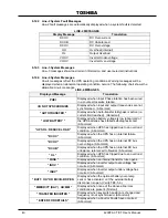
The illustration below shows a graphical representation of the UPS battery recharge  


process after a full discharge. 


The recharge process usually consists of three steps. During the first step, the charging 
current is maintained at approximately 4.0 amperes for the 15/25/30 kVA with internal 
batteries, 10.0 amperes for the 15/25/30 kVA with internal transformer and approximately 
11.5 amperes for all 50 kVA models. This current is the maximum value that can be used 
to charge the batteries (for minimal recharge time) while assuring safety and long battery 
life. In the second step, constant-voltage control starts and current gradually decreases as 
the batteries charge to their normal fully charged state.  In the third step, a slight "trickle" 
current continues to flow into the batteries to keep them fully charged and "floating" at the 
normal DC Voltage level. A full recharge usually  requires approximately 24-72 hours (90% 
recharge in 10 X discharge time) after a  complete discharge.  


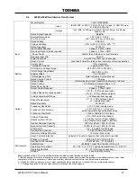
The following chart shows the rated maximum and minimum battery voltages, and the 


charge current for each of the sizes while the unit is maintained in a 75 °F (24 

°

C) ambient. 


Rated Battery Voltages 

15/25/30 kVA  

50 kVA 

Model 

Internal 

Battery 

Internal 

Transformer 

Internal 

Battery 

Internal 

Transformer 

V float 

324.0 VDC 

324 VDC 

324 VDC 

V min 

216 VDC 

216 VDC 

216 VDC 

I charge 

4.0 A 

10.0 A 

11.5 Amps 


36 


4200FA CT/XT User’s Manual 

Summary of Contents for 4200 FA CT

Page 1: ...TOSHIBA UNINTERRUPTIBLE POWER SYSTEM THREE PHASE 15 25 30 50 kVA UPS 4200FA CT XT User s Manual Document Number 53878 008 Date May 2008 ...

Page 2: ...TOSHIBA 4200FA CT XT User s Manual ...

Page 3: ...sformer USER S MANUAL FOR MODELS C42F3F150X MBN C42F3F150F MBN C42 3 150 MXN C42F3F250X MBN C42F3F250F MBN C42 3 250 MXN T42F3F300X MBN T42F3F300F MBN T42 3 300 MXN T42F3F500XAMBN T42F3F500F MBN T42 3 500 MXN TOSHIBA INTERNATIONAL CORPORATION INDUSTRIAL DIVISION 13131 West Little York Road Houston TX 77041 9990 4200FA CT XT User s Manual ...

Page 4: ...TOSHIBA 4200FA CT XT User s Manual ...

Page 5: ...y Electrical or mechanical modifications to this equipment without prior written consent of the TOSHIBA will void all warranties and may void UL CUL listing Unauthorized modifications may also result in equipment damage personal injury or loss of life UNINTERRUPTIBLE POWER SYSTEM If additional information or technical assistance is required call TOSHIBA Customer Support Center toll free at 1 877 8...

Page 6: ...s appearing in this manual are registered trademarks of their respective owners TOSHIBA shall not be liable for technical or editorial omissions or mistakes in this manual Nor shall it be liable for incidental or consequential damages resulting from the use of information contained in this manual This manual is copyrighted No part of this manual may be photocopied or reproduced in any form without...

Page 7: ...Circuit and External Battery Interface Connections 15 25 30 kVA 19 4 2 1 Recommended Wire Size and Torque Requirements 19 4 3 Power Connections 50 kVA 20 4 3 1 Recommended Wire Size and Torque Requirements 21 4 3 2 Power Connection Cable Routing and Conduit Placement 50 kVA 22 4 4 Control Circuit and External Interface Connections 50 kVA 23 4 4 1 Recommended Wire Size and Torque Requirements 23 4 ...

Page 8: ...7 6 18 5 MENU F1 ENTER UP DOWN Keys 47 6 18 6 BATT TEST Key 47 6 18 7 BUZZ STOP Key 48 6 18 8 RESET Key 48 6 19 Menu Data Screens 49 6 19 1 Settings for Calendar and Clock 49 6 19 2 Adjusting the Buzzer Volume 49 6 19 3 Settings for Display Duration 49 6 19 4 Run Switch Select 50 6 19 5 Serial Com Station Address 50 6 19 6 Output Voltage Adjustment 51 6 19 7 Equalize Charge Mode Select 51 6 19 8 R...

Page 9: ...losed in a triangle which precedes the word CAUTION The Caution warning symbol is used to indicate situations and conditions that can cause operator injury and or equipment damage CAUTION 3 Attention warning The attention warning symbol is an exclamation mark enclosed in a triangle which precedes the word ATTENTION The Attention warning symbol is used to indicate situations and conditions that can...

Page 10: ...o the equipment DO NOT remove or cover any of the labels If the labels are damaged or if additional labels are required contact your TOSHIBA representative for additional labels The following are examples of the warning labels that may be found on the equipment The labels are there to provide useful information or to indicate an imminently hazardous situation that may result in serious injury seve...

Page 11: ...e done in accordance with National Electrical Code and any other state or local codes Proper grounding and conductor sizing must be installed for safe operation During operation keep all covers in place and cabinet doors shut When performing visual inspections and maintenance if possible be sure the UPS is turned off and the incoming AC feed is turned off and locked out If it is necessary to make ...

Page 12: ...TOSHIBA NOTE This Label for Battery Units Only 4 4200FA CT XT User s Manual ...

Page 13: ...on manual 2 Be trained and authorized to safely energize de energize ground lockout and tag circuits and equipment and clear faults in accordance with established safety practices 3 Be trained in the proper care and use of protective equipment such as safety shoes rubber gloves hard hats safety glasses face shields flash clothing etc in accordance with established safety practices 4 Be trained in ...

Page 14: ...lode CAUTION Do not open or mutilate the batteries Released electrolyte is toxic and harmful to the eyes and skin CAUTION This unit contains sealed lead acid batteries An annual preventative maintenance should be performed by an authorized technician Failure to do so could result in batteries exploding and emitting gasses and or flame CAUTION Do not open or mutilate the batteries Released electrol...

Page 15: ...atic electricity 10 Do not attempt to open the batteries in order to add water or sample the specific gravity of the electrolyte The batteries are valve regulated lead acid type and such servicing is not possible without damaging the battery 11 Use proper lifting means when moving batteries and wear all appropriate safety clothing and equipment 12 Dispose of lead acid batteries through proper chan...

Page 16: ... notice contient des instructions importantes concernant la sécurté ATTENTION Un battery puet présenter un risque de choc électrique de brûlure par transfert d énergie ATTENTION L élimination des batteries est règlementèe Consultar les codes locaux à cet effet 8 4200FA CT XT User s Manual ...

Page 17: ...act efficient high performance unit The UPS assures safe reliable operation of critical office equipment ranging from personal computers to mini computers to local area networks LAN All units feature an audible alarm that sounds if the battery voltage drops below the standard during use This is an additional aid to help in retaining valuable data and equipment All units are capable of interfacing ...

Page 18: ...nd foam packing material TOP HEAVY EQUIPMENT IMPROPER LIFTING CAN RESULT IN INJURY OR DEATH LIFT AND MOVE CAREFULLY AND ONLY WITH ADEQUATE EQUIPMENT AND TRAINED PERSONNEL THIS EQUIPMENT WILL TIP OVER EASILY UNTIL FIXED IN PLACE DANGER 3 Place the tie brackets in the slots at the lower end of the ramps SLOWLY roll the unit down the ramp 2 Unbolt the rails from both the unit and the shipping pallet ...

Page 19: ...EQUIPMENT WILL TIP OVER EASILY UNTIL FIXED IN PLACE 1 Remove packing material 3 Place the tie brackets in the slots at the lower end of the ramps SLOWLY roll the unit down the ramp 1a For international units remove the screws that attach the shipping crate to the pallet Remove the crate and foam packing material 2 Unbolt the rails from both the unit and the shipping pallet Place the rails on the f...

Page 20: ...s described in section 6 15 of this manual Storing 1 Store within a temperature range of 4 104 F 20 40 C 2 For best results store the UPS in the original shipping container and place on a wood or metal pallet 3 The optimum storage temperature is 70 F 21 C Higher ambient temperatures cause UPS batteries to need recharging more frequently 4 If stored in an ambient temperature under 68 F 20 C recharg...

Page 21: ...he unit in areas that are exposed to direct sunlight or contaminated areas subject to high levels of airborne dust metal particles or flammable gasses FRONT 20 500mm Fig 3 1 Verify the ventilation and air conditioning system at the site is capable of removing the heat generated by the UPS Ambient temperature range for operating the UPS is 32 104 F 0 40 C 77 F 25 C is the recommended operating temp...

Page 22: ... starting current or a long starting time such as vacuum cleaners and machine tools 6 Do not insert metal objects or combustible materials in the unit s ventilation slots 7 Do not place hang or paste any objects on the top or on the exterior surfaces of the UPS 8 The capacitors of the UPS maintain a residual charge for a while after turning off the UPS The required discharge time for each UPS is p...

Page 23: ...he UPS could be damaged if the unit is not fully powered down before the breaker is reset 4 0 UPS Connections 4 1 Power Connections 4 1 1 Power Connections 15 25 30 kVA with Internal Batteries The following illustrates the wiring connections from the power distribution panel not part of the UPS to the terminal block of the 15 25 30 kVA UPS Models Ensure the three phase commercial power input is co...

Page 24: ... three phase commercial power input is connected for clockwise rotation The UPS output function is disabled if the input power is not phased for clockwise rotation Customer provided breaker for units with optional Bypass Input CUSTOMER PROVIDED AC DISTRIBUTION PANEL TO BATTERY SYSTEM GND TB4 INPUT GROUND RESISTANCE LESS THAN 10 OHMS TB1 Optional Bypass Input 3 Phase 3 Wire 208 V requires 3 Phase 4...

Page 25: ...7 240 V 8 N A 51 N A 4 N A 51 N A 2 N A 87 N A 220 380 V 10 8 35 51 8 4 51 51 6 2 51 87 230 400 V 10 8 35 51 8 4 51 51 6 2 51 87 240 415 V 10 8 35 51 8 4 51 51 6 2 51 87 277 480 V 10 8 35 51 8 6 51 51 6 2 51 87 600 V 10 N A 35 N A 10 N A 35 N A 10 N A 35 N A Note Neutral Conductors are rated 1 73 or 200 of phase conductors per NEC Maximum Wire Size is 2 AWG 15 kVA 25 kVA 30 kVA Input Output GND AW...

Page 26: ...ss of the 15 25 30 kVA Note 1 Input and Output conductors shall be installed in separate conduits and installed in accordance with the latest edition of NEC and the Local Authority having jurisdiction 2 Battery conductors shall be installed in a separate conduit and be of low resistance type CONDUIT MOUNTING PANEL INPUT CONDUIT OUTPUT CONDUIT BATTERY CONDUIT 18 4200FA CT XT User s Manual ...

Page 27: ...op 11 Bypass 12 COMMON 13 EPO 14 EPO 15 24 Not Used 4 2 1 Recommended Wire Size and Torque Requirements UPS Control and Battery Interface 15 25 30 kVA Minimum Wire Size and Torque Requirements UPS Control and Battery Interface Circuits USE MINIMUM 75 C COPPER WIRING Wire Size AWG TERMINAL TERMINAL 15 kVA 25 kVA 30 kVA TIGHTENING TORQUE UPS CONTROL CIRCUITS 1 24 14 16 14 16 14 16 8 in lbs BATTERY C...

Page 28: ...nel not part of the UPS to the terminal block of the 50 kVA UPS Model Optional Bypass Input 3 phase 3 wire H1 H2 H3 N H1 H2 H3 N L1 L2 L3 N OUTPUT 3 phase 4 wire INPUT 3 phase 3 wire TB1 TB4 208 V requires 3 phase 4 wire Optional Bypass Input 3 phase 3 wire 208 V requires 3 phase 4 wire 20 4200FA CT XT User s Manual ...

Page 29: ...Output is 1 0 AWG Neutral Conductors are rated 1 73 or 200 of phase conductors per NEC Maximum Wire Size for Neutral is 250MCM 50 kVA Input Output GND AWG Tightening Torque 208 240 VAC 6 200 in lbs 380 480 VAC 6 200 in lbs 600 VAC 8 200 in lbs Battery 50 kVA AWG Tightening Torque 250MCM 200 in lbs Maximum Wire Size for Battery is 250MCM Minimum Wire Size and Torque requirements UPS Optional Bypass...

Page 30: ...ing and Conduit Placement 50 kVA The following illustrates the proper cable routing that should be followed during the power connection process for the 50kVA Bottom Conduit Entry Removable cover for conduit access 22 4200FA CT XT User s Manual ...

Page 31: ...pply 7 P24A3 8 Remote Run 9 P24A3 10 Remote Stop 11 Bypass 12 COMMON 13 EPO 14 EPO 15 18 Not Used 4 4 1 Recommended Wire Size and Torque Requirements UPS Control and Battery Interface 50 kVA Minimum Wire Size and Torque Requirements UPS Control and Battery Interface Circuits USE MINIMUM 75 C COPPER WIRING 50 kVA TERMINAL TERMINAL AWG TIGHTENING TORQUE UPS CONTROL CIRCUITS 1 24 14 16 8 in lbs BATTE...

Page 32: ...ch signal and the associated DB9 connector pin out 5 System Common 6 Bypass Active Fault Signal Detect 1 2 8 UPS On line 7 Battery Voltage Low Battery Discharge 9 4 DB9 Male Connector Outline facing connector 1 2 3 4 5 6 7 8 9 Notes 1 Pin switches are shown in their inactive states Example if battery voltage is low pin 7 will be connected to System Common 2 Contacts are rated at 30 VDC 0 1 amps 12...

Page 33: ...ed Overload allowable time exceeded Output Over Voltage during Normal Mode Output Under Voltage during Normal Mode The connector pin assignment and female connector outline are illustrated below Pin I O Symbol Description 1 This pin is not used 2 Input RXD Receive Data 3 Output TXD Transmit Data 4 Output DTR Data Terminal Ready 5 SG Signal Ground 6 Input DSR Data Set Ready 7 Output RTS Request To ...

Page 34: ...ee running mode Frequency Synchronous 0 5 1 0 1 5 Hz 1 0 Hz std switch selectable by qualified technician Frequency Slew Rate 1 Hz s to 3Hz s in 0 5 Hz steps Voltage Transients Recovery time 50 ms 5 100 load step change 3 loss or return of input voltage 8 transfer from bypass to inverter Inverter Overload Capacity 125 for 90 sec 150 for 30 sec Bypass Overload Capacity 1000 for 10 ms 125 for 10 min...

Page 35: ...100 balanced load 4 unbalanced load Rated Frequency 50 60 Hz Frequency Regulation 0 1 in free running mode Frequency Synchronous 0 5 1 0 1 5 Hz 1 0 Hz std switch selectable by qualified technician Frequency Slew Rate 1 Hz s to 3Hz s in 0 5 Hz steps Voltage Transients Recovery time 50 ms 5 100 load step change 3 loss or return of input voltage 8 transfer from bypass to inverter Inverter Overload Ca...

Page 36: ...nchronous 0 5 1 0 1 5 Hz 1 0 Hz std switch selectable by qualified technician Frequency Slew Rate 1 Hz s to 3Hz s in 0 5 Hz steps Voltage Transients Recovery time 50 ms 5 100 load step change 3 loss or return of input voltage 8 transfer of bypass to inverter Inverter Overload Capacity 125 for 90 sec 150 for 30 sec Bypass Overload Capacity 1000 for 10 ms 125 for 10 min Crest Factor 2 5 3 0 within t...

Page 37: ... 2 0 100 balanced load 4 unbalanced load Rated Frequency 50 60 Hz Frequency Regulation 0 1 in free running mode Frequency Synchronous 0 5 1 0 1 5 Hz 1 0 Hz std switch selectable by qualified technician Frequency Slew Rate 1 Hz s to 3Hz s in 0 5 Hz steps Voltage Transients Recovery time 50 ms 5 100 load step change 3 loss or return of input voltage 8 transfer from bypass to inverter Inverter Overlo...

Page 38: ...equency Regulation 0 1 in free running mode Frequency Synchronous 0 5 1 0 1 5 Hz 1 0 Hz std switch selectable by qualified technician Frequency Slew Rate 1 Hz s to 3Hz s in 0 5 Hz steps Voltage Transients Recovery time 50 ms 5 100 load step change 3 loss or return of input voltage 8 transfer from bypass to inverter Inverter Overload Capacity 125 for 90 sec 150 for 30 sec Bypass Overload Capacity 1...

Page 39: ... Rated Frequency 50 60 Hz Frequency Regulation 0 1 in free running mode Frequency Synchronous 0 5 1 0 1 5 Hz 1 0 Hz std switch selectable by qualified technician Frequency Slew Rate 1 Hz s to 3Hz s in 0 5 Hz steps Voltage Transients Recovery time 50 ms 5 100 load step change 3 loss or return of input voltage 8 transfer from bypass to inverter Inverter Overload Capacity 125 for 90 sec 150 for 30 se...

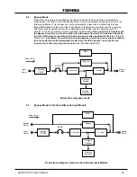
Page 40: ...ins a constant voltage and provides current limiting for charging the batteries It also supplies a DC voltage of the proper level to the inverter section The inverter section generates a high quality sine wave output voltage The batteries are maintained in a constantly charged state when the UPS is in the Normal Operation Mode Converter Inverter Bypass Charger Chopper Isolating XFMR External Batte...

Page 41: ...fault condition then the power flow must be transferred manually from the UPS s Bypass circuit back to the Inverter circuit after repairing the fault see Start up Procedure If the power flow is transferred to the Bypass circuit due to an overload condition then the power flow will automatically transfer from the UPS s Bypass circuit back to the Inverter circuit after removing the overload see Over...

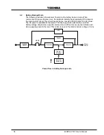
Page 42: ... circuit This circuit inverts hence Inverter the DC power into AC po The AC power is available at the output This back up process will continue until the battery voltage drops below a specific minimum level When this occurs the batteries will stop supplying power to the load This minimum level is the rated minimum voltage V min Converter Inverter Bypass Charger Chopper Isolating XFMR External Batt...

Page 43: ...re and other variables CAUTION Contact TOSHIBA when using other than TOSHIBA designed Battery Systems to determine proper compliance Using other systems could void Warranty and or Safety Certifications The following illustration graphically shows the battery discharge process at full load conditions 6 6 Battery Low Voltage Tolerances Excessive discharge will cause the UPS battery voltage to drop b...

Page 44: ...tant voltage control starts and current gradually decreases as the batteries charge to their normal fully charged state In the third step a slight trickle current continues to flow into the batteries to keep them fully charged and floating at the normal DC Voltage level A full recharge usually requires approximately 24 72 hours 90 recharge in 10 X discharge time after a complete discharge The foll...

Page 45: ...O Emergency Power Off Function These units are equipped with terminals for receiving an EPO Emergency Power Off closed contact switch command from two locations 1 a remote location and 2 from a front panel mounted EPO switch This safety feature enables quick shutdown of the UPS AC output and battery circuits Usually the EPO switch is installed in a central location that is easily accessible to per...

Page 46: ...mp to be on On when the UPS has normal AC input power that is within tolerance If there is an input power failure this LED is off If there is no power failure and the input voltage is in an over voltage condition the AC IN LED will flicker on and off rapidly 0 4 sec on and 0 4 sec off If there is no power failure and the input voltage is in an under voltage condition the AC IN LED will be off On w...

Page 47: ... conjunction with the LED display and the audible alarms for total system monitoring The LCD displays certain information only on specific lines of the display The UPS operating mode and conditions determines the information shown These messages are shown in the following line message charts 6 12 1 Line 1 System Messages Line 1 messages are based on the operating mode The following chart shows all...

Page 48: ...TRANSFER Displayed when battery voltage is low abnormal or the UPS batteries have failed self diagnostic test Abnormal LOW BATTERY Displayed when UPS has tripped due to an overload condition Abnormal UPS OL REDUCE LOAD Displayed when the UPS has an internal failure Abnormal DCOC Displayed when the UPS has an internal DC bus over voltage Abnormal DCOV Displayed when the UPS has an internal DC bus u...

Page 49: ...ould display the following message UPS START UP PLEASE WAIT 3 With the key switch in the STOP position the AC IN and the BYP lamp will be on and the LCD screen should display the following message BYPASS OPERATION OUTPUT VOLTAGE 208 V CURRENT 100 100 100 DATE DAY TIME 4 Turn the Key Switch to RUN and the UPS automatically performs a controlled system battery test Note The Automatic Battery Test is...

Page 50: ...lamp will be on and the LCD screen should display the following message BYPASS OPERATION OUTPUT VOLTAGE 208 V CURRENT 100 80 90 DATE DAY TIME The UPS battery charging circuit is now activated Move the STOP RUN key switch to the RUN position The inverter will then start and the UPS will transfer to the Normal Operating Mode Both the AC IN and the INV lamp will be on The following system message is ...

Page 51: ...power through the Bypass circuit The green AC IN lamp is on and the green BYP lamp is on The LCD screen shows the following message BYPASS OPERATION OUTPUT VOLTAGE 208 V CURRENT 100 100 100 DATE DAY TIME Move the Circuit Breaker to the off position Power is removed from the UPS and to any attached loads All lamps are off and the LCD screen shows the following message as long as sufficient power re...

Page 52: ...tive 2 Verify that step one above is followed and that the BYP LED indicator on the front panel is illuminated 3 Locate the maintenance bypass rotary cam switch middle of inner front panel of the UPS slowly rotate the cam switch clockwise to the BYPASS MODE position 4 Turn off MCCB breaker labeled MAIN POWER SWITCH The unit is now in the Maintenance Bypass mode and may be serviced For units with i...

Page 53: ...PS input conditions OUT Output Press to display UPS output conditions BATT TEST Battery Test Press to execute On Line Battery test BUZZ STOP Buzzer Stop Press to stop the audible alert buzzer MENU Menu Press to display the main user selection menu ENTER Enter Press to confirm user selected command or action RESET Reset Press to reset UPS panel s message display area Up Arrow Press to forward throu...

Page 54: ...T 100 100 99 DATE DAY TIME If an AC input power failure occurs and no abnormal operating conditions are present the UPS switches to standard Battery Backup Mode The following system message is displayed BATTERY BACKUP OUTPUT VOLTAGE 208 V CURRENT 100 100 99 DATE DAY TIME 6 18 2 IN When the IN key is pressed during normal AC Input Mode of operation the LCD screen displays details about the unit s i...

Page 55: ...anges to the adjustment screen for that menu item Press up arrow to move display to previously available item Press down arrow to move display to next available item From the adjustment screen if the MENU key is pressed any changes are discarded and the display returns to the regular menu screen with the previous data values shown If the ENTER key is pressed from the adjustment screen the changes ...

Page 56: ... key has no effect on the LCD screen display However if the UPS alarm buzzer is on pressing this key will silence it If the alarm buzzer is not on pressing this key has no effect 6 18 8 RESET Key The RESET key function is used to Reset the LCD display board software should a system lock up occur The reset does not reset the variables in the memory Use of the RESET function is very important when a...

Page 57: ...creen display BUZZER VOLUME ADJUST LOUD MEDIUM SOFT F1 DATA SET MODE Δ PRV NEXT SCREEN Press the F1 key to display the following active adjustment screen BUZZER VOLUME ADJUST LOUD MEDIUM SOFT Δ CHANGE DATA ENTER ACCEPT CHANGE Press the up or down arrow key to move the marker between the three buzzer volume levels Press ENTER key to confirm the change or press MENU key to discard any changes and re...

Page 58: ...tch Select setting screen display RUN SWITCH SELECT LOCAL REMOTE F1 DATA SET MODE Δ PRV NEXT SCREEN Press the F1 key to display the following active adjustment screen RUN SWITCH SELECT LOCAL REMOTE Δ CHANGE DATA ENTER ACCEPT CHANGE Press the up or down arrow key to move the marker between the two RUN SWITCH selections Press the ENTER key to save the change or press the MENU key to exit to the main...

Page 59: ...he allowable voltage adjustment parameter values Press the up and down arrow keys to adjust the setting from between 5 volts This will cause the unit s output voltage to adjust to within 2 of its nominal value If the inverter is not running and the output voltage cannot be adjusted the following message will be displayed OUTPUT VOLT ADJUST ADJUST PROHIBITED DATA CANNOT CHANGE Δ PRV NEXT SCREEN Pre...

Page 60: ... key to abandon the operation and return to the menu data screen 6 20 Overload Operation When the UPS is operating and an overload condition is first detected the following Overload Warning screen is displayed UPS ON LINE OUTPUT VOLTAGE V OUTPUT CURRENT UPS OL REDUCE LOAD After a period of time if the overload is still not reduced and the STOP RUN key switch is in the RUN position the UPS will aut...

Page 61: ... STOP position when the UPS s wait period is complete then the following screen will be displayed BYPASS OPERATION OUTPUT VOLATAGE V CURRENT 100 100 100 DATE DAY TIME If the STOP RUN key switch remains in the RUN position when the UPS s wait period is complete then the following screen will be displayed UPS ON LINE OUTPUT VOLTAGE 208 V CURRENT 100 100 99 DATE DAY TIME 6 21 Backup History and Fault...

Page 62: ...or down arrow keys to display the Fault Count screen TOTAL FAULT COUNT TIMES F1 FOR DETAILS Δ TO SCROLL Press the F1 key to display the record relating to the first fault FAULT HISTORY 1 Date Time fault code Δ EXIT F1 NEXT Press the F1 key again to display the record relating to each subsequent fault FAULT HISTORY Date Time fault code Δ EXIT F1 NEXT Press the up or down arrow keys to return to the...

Page 63: ...opped Inverter Overload Transfer to bypass Inverter stopped Bypass Overload Inverter Chopper and Bypass stopped Audible Alarm Yes See Audible Alarm Functions Visible Alarm Red Fault Lamp on Inverter OL No Fault Lamp Bypass OL Fault Lamp on Relay Contact Alarm Fault Relay closed Bypass Relay closed Inverter OL Bypass Relay closed Bypass OL Bypass Relay open and Fault relay closed Auto Retransfer No...

Page 64: ...ep begins the internal self checks within the processor logic 6 Output Voltage Check The output voltages are checked to verify they are within range 7 EPO Emergency Power Off The EPO is operated to verify its operation in case of an emergency 8 Load Testing Performed if load is available 9 Generator Testing Performed if Generator is available 10 Internal External Maintenance Bypass This verifies t...

Page 65: ...same time to eliminate the possibility of multiple failures due to resistances of the batteries Recommended Quarterly Maintenance A Visual Checks 1 Leakage 2 Corrosion on positive terminal B Check battery temperature at the negative terminal C Measure and record the system float charging voltage D Measure and record the individual unit s float charging voltage Recommended Semi Annual maintenance A...

Page 66: ...TOSHIBA 9 0 External Dimensions Shipping Dimensions Weights 9 1 External Dimensions 15 25 30 kVA 15 25 30 kVA 36 3 in 922 mm 58 4200FA CT XT User s Manual ...

Page 67: ...TOSHIBA 9 2 External Dimensions 50kVA 35 5 in 901 mm 59 3 in 1506 mm 38 3 in 972 mm 4200FA CT XT User s Manual 59 ...

Page 68: ...63 69 9 178 Height with packing material 67 3 171 69 9 178 Model Shipping Weight Standard Pounds Kilograms Shipping Weight with crate Pounds Kilograms 15 30 kVA with internal battery 1015 460 1090 494 15 30 kVA with no internal transformer or battery 815 370 890 404 15 30 kVA with 1 internal transformer 900 408 975 442 15 30 kVA with 2 internal transformers 1100 499 1175 533 50 kVA with internal b...

Page 69: ......

Page 70: ...INDUSTRIAL DIVISION 13131 West Little York Rd Houston TX 77041 Tel 713 466 0277 Fax 713 466 8773 US 877 867 8773 Canada 800 872 2192 Mexico 01 800 527 1204 www toshiba com ind Printed in the U S A ...

Reviews: