background image

TOSHIBA

34

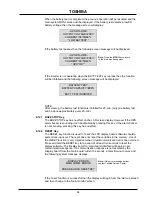
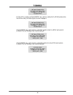
When the battery test is completed, the previous operation will be resumed and the
main system MONI screen will be displayed. If the battery test detects a low DC
battery voltage, then the message screen will display:  

- UPS ON-LINE -

OUTPUT VOLTAGE=208V

CURRENT=38/55/48%

* LOW BATTERY *

If the battery test passes then the following screen message will be displayed:  

- UPS ON-LINE -

OUTPUT VOLTAGE=208V

CURRENT=38/55/48%

* UPS "OK" *

If the inverter is not operating when the BATT TEST key is press then the function
will be inhibited and the following screen message will be displayed: 
 

- BATTERY TEST -

BATTERY CAPACITY=###%

BATT. TEST INHIBITED

NOTE:
After start-up, the battery test function is inhibited for 20-min. (only one battery test
can be done approximately every 20-min.).

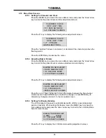
6.14.7  BUZZ STOP Key

The BUZZ STOP key has no effect on the LCD screen display. However if the UPS
alarm buzzer is sounding it can be disabled by pressing this key. If the alarm buzzer
is not sounding, pressing this key has no effect.

6.14.8  RESET Key

The RESET key function is used to 'reset' the LCD display board software should a
system lock-up occur. The reset does not reset the variables in the memory. 

Use of

the RESET function is very important when a fatal communication error has occurred.

Press and hold the RESET key for a period of at least five seconds to reset the
display software. The 'display board' to 'main board' interface will begin a new
communication sequence. If a communication response is not received by the
'display board' from the 'main board' within 15 seconds, a fatal time-out occurs and
the following system message displays:

- DISPLAY ERROR -

MAIN COMM. ERROR

PRESS & HOLD RESET KEY

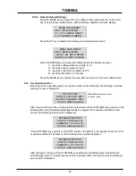
If the 'reset' function is successful then the display will begin from the 'start-up screen'
and then change to the 'main monitor' screen.

Note:

 Press the 

MONI

 key to return

to the main monitoring menu.

Note:

 If this error message persist

contact Toshiba Service Center.

Summary of Contents for 4200 series

Page 1: ...TOSHIBA UNINTERRUPTIBLE POWER SYSTEM THREE PHASE 75 100kVA UPS 4200 SERIES MANUFACTURED IN THE U S A OPERATION MANUAL Part Number 51751 001 Date March 2003 ...

Page 2: ...0 SERIES THREE PHASE 75 100 kVA UNINTERUPTIBLE POWER SYSTEM OPERATION MANUAL FOR MODELS U42B3F750C6CB U42B3F10KC6CB TOSHIBA INTERNATIONAL CORPORATION INDUSTRIAL DIVISION 13131 West Little York Rd Houston Texas 77041 ...

Page 3: ...ision Should further information be desired or should particular problems arise which are not covered sufficiently for the purchaser s purposes the matter should be referred to the local Toshiba sales office The contents of this instruction manual shall not become a part of or modify any prior or existing equipment commitment or relationship The sales contract contains the entire obligation of Tos...

Page 4: ... COULD result in injury Equipment damage may also occur CAUTION 4 Attention warnings The attention warning symbol is an exclamation mark enclosed in a triangle which precedes the 3 16 high letters spelling the word ATTENTION The Attention warning symbol is used to indicate situations and conditions that COULD cause operator injury and or equipment damage ATTENTION Other warning symbols may appear ...

Page 5: ... Control and Battery Interface 16 4 3 Communication Interface 17 4 3 1 Remote Contact IBM AS 400 17 4 3 2 RS 232C 18 4 3 3 UPS Shutdown via RS 232C 18 5 0 Specifications 19 5 1 4200 Series Specifications 75 and 100kVA Standard 208Vac Output 19 6 0 Operating the UPS 20 6 1 Operating the UPS 20 6 1 1 AC Input Mode normal operation 20 6 1 2 Circuit bypass Mode 20 6 1 3 Battery Backup Mode 21 6 2 Batt...

Page 6: ...6 6 15 5 Serial Com Station Address 36 6 15 6 Output Voltage Adjustment 37 6 15 7 Charge Mode Select 37 6 15 8 Reset to Default Settings 38 6 16 Overload Operation 38 39 7 0 UPS Protection System 40 7 1 System Protection Features 40 7 2 System Protection Functions 40 8 0 Preventive and Scheduled Maintenance Part Replacement 41 8 1 Preventive Maintenance 41 8 2 Parts Replacement 41 9 0 External Lay...

Page 7: ...ified Toshiba Representative who is knowledgeable of batteries and the required precautions should only perform servicing of the batteries Keep unauthorized personnel away from batteries Refer to the Battery System Manual when scheduling maintenance or battery replacement CAUTION Misuse of this equipment could result in human injury and equipment damage In no event will Toshiba Corporation be resp...

Page 8: ...nds are removed during installation and maintenance 7 Verify circuit polarities prior to making connections 8 Disconnect charging source and load prior to connecting or disconnecting terminals 9 VRLA batteries contain an explosive mixture of hydrogen gas Do not smoke or create a flame or spark in the immediate area of the batteries This includes static electricity from the body 10 Do not attempt t...

Page 9: ...Series of on line Uninterruptible power systems UPS provide continuous computer grade AC power in a compact efficient high performance unit The UPS assures safe reliable operation of critical office equipment ranging from personal computers to mini computers to local area networks LAN All units feature an audible alarm that sounds if the battery voltage drops below standard during use This is an a...

Page 10: ...ove the crate and foam packing material 2 Unbolt the rails from both the unit and the shipping pallet Place the rails on the front of the pallet as shown in figure 2 2 and figure 2 3 Use the four 1 2x3 bolts used to secure the rails to the shipping pallet to attach the rails as shown to the front of the pallet 3 Place the tie brackets as shown in figure 2 3 in the slots at the lower end of the ram...

Page 11: ... system shutdown as described in section 6 12 of this manual Storing 1 Store within a temperature range of 20 to 40 C 4 to 104 F 2 For best results store the UPS in the original shipping container and place on a wood or metal pallet 3 The optimum storage temperature is 21 C 70 F Higher ambient temperatures cause UPS batteries to need recharging more frequently 4 If stored in an ambient temperature...

Page 12: ... direct sunlight or contaminated areas subject to high levels of airborne dust metal particles or flammable gasses 5 Verify the ventilation and air conditioning system at the site is capable of removing the heat generated by the UPS unit see Section 5 1 Specifications Environment Ambient temperature range for operating the UPS is 0 to 40 C 32 104 F 25 C 77 F is the recommended operating temperatur...

Page 13: ... 10 to 15 of the rated input voltage The input frequency must be within the rated input frequency range Voltages and frequencies outside of the permissible range may cause internal protection devices to activate 3 The UPS should not be used with a load whose rated input is greater than the rated UPS output 4 Do not use the UPS to provide power to motors that require high starting current or a long...

Page 14: ... UPS Connections 4 1 Power Connections 75 and 100kVA The following illustrates the wiring connections to the Input and Output Terminations points for the 75 and 100kVA UPS Models 4 1 1 H1 H2 H3 Input N L1 L2 L3 GND N ...

Page 15: ...lbs L1 L3 N AWG H1 H3 AWG N Tightening Torque in lbs L1 L3 N 208 120 300MCM 400MCM 325 375 350MCM 700MCM 325 375 All wire sizes are per the NEC 75kVA 100kVA Output L1 L2 L3 N AWG L1 L3 AWG N Tightening Torque in lbs L1 L3 N AWG L1 L3 AWG N Tightening Torque in lbs L1 L3 N 208 120 300MCM 400MCM 325 375 350MCM 700MCM 325 375 Neutral Conductors are rated 1 73 or 200 of phase conductors per NEC 75kVA ...

Page 16: ...e 75 and 100kVA Note 1 Input and Output conductors shall be installed in separate conduits and installed in accordance with the latest edition of NEC and the authority having jurisdiction 2 Battery conductors shall be installed in a separate conduit and be of low resistance type Top Conduit Entry Main Input Main MCCB Main Input N Output Ground Bottom Conduit Entry ...

Page 17: ... Size and Tightening Torque UPS Control and Battery Interface Minimum Wire Size and Tightening Torque for UPS Control and Battery Interface Circuits USE MINIMUM 75 C COPPER WIRING TERMINAL TERMINAL 75kVA 100kVA AWG TIGHTENING TORQUE AWG TIGHTENING TORQUE UPS CONTROL CIRCUITS 1 24 14 16 8 in lbs 14 16 8 in lbs BATTERY CONTROL CIRCUITS 3 6 14 16 8 in lbs 14 16 8 in lbs Indicates Class 1 wiring metho...

Page 18: ...ows the contact state and pin assignment for each signal and the associated DB9 connector pin out Notes 1 Pin switches are shown in their inactive states if battery voltage is low pin 7 will be connected to System Common 2 Contacts are resistive loads rated at 30 Vdc 0 1 amp 125VAC 3A 3 Pin number 3 is not used 5 System Common 6 Bypass Active Fault Signal Detect 1 2 8 UPS On line 7 Battery Voltage...

Page 19: ...Over Current Overheat Overload Being Timed Overload allowable time exceeded Output Over Voltage during Normal Mode Output Under Voltage during Normal Mode The connector pin assignment and female connector outline are illustrated below DB9 Female Connector Outline facing connector Pin I O Symbol Description 1 This pin is not used 2 Input RXD Receive Data 3 Output TXD Transmit Data 4 Output DTR Data...

Page 20: ... free running mode Frequency Synchronous 5 1 0 1 5 Hz 1 0 Hz std switch selectable by qualified technician Frequency Slew Rate 1 Hz s to 3Hz s Voltage Transients Recovery time 50 msec 5 100 load step change 3 loss or return of input voltage 8 transfer of bypass to inverter Inverter Overload Capacity 125 30 sec 150 5sec Bypass Overload Capacity 1000 10msec 125 10 min Crest Factor 2 5 Neutral Line C...

Page 21: ...in circuit to the units bypass circuit Power flow through the bypass is shown in the following illustration This changeover occurs automatically in less than 4 milliseconds in phase The switching period is not long enough to cause interruptions to occur in most loads If the power flow is transferred to the bypass circuit because of an overload and that overload condition ends within a specified pe...

Page 22: ...rge process is explained in Section 6 2 Power flow in battery backup mode for the 75 and 100 kVA models 6 2 Battery Backup Time and Discharge Process The UPS system when used in conjunction with a Toshiba designed Battery System is designed to provide several minutes of back up time for the 75 100 kVA models Refer to the Battery System Manual for back up times These times are valid when the unit i...

Page 23: ...s The chart shown below lists the voltage level at which each UPS unit s low voltage alarm will sound and also at what level the low voltage condition will cause the unit to automatically shut down 75kVA 100kVA Nominal Voltage 240Vdc 324Vdc Alarm Voltage 228Vdc 308Vdc Shutdown Voltage min 210Vdc 283Vdc 6 4 Battery Recharging The illustration below shows a graphical representation of the UPS batter...

Page 24: ... period a slight trickle current continues to flow into the batteries to keep them fully charged and floating at the normal DC Voltage level A full recharge usually requires approximately 24 hours 90 recharge in 10 hours after a complete discharge The following chart shows the rated maximum and minimum battery voltages and the charge current for each of the sizes while the unit is maintained in a ...

Page 25: ... same whether the UPS unit is in the AC input mode see Section 6 1 1 battery backup mode see Section 6 1 3 or the circuit bypass mode see Section 6 1 2 See EMERGENCY OFF screen in Section 6 1 2 Shutdown Procedure The following figure shows the UPS condition after application of the EPO switch Use the Start up Procedure see Section 6 11 for restarting the unit 6 7 Audible Alarm Functions Audible al...

Page 26: ... BATT lamp will flicker on and off slowly 1 2 sec on and 1 2 sec off The BATT lamp will go off if the battery voltage reaches the shutdown level during the battery discharge mode This red LED lamp is on when the UPS is in a fault condition 6 8 1 Light Emitting Diode LED System Status The following chart shows the UPS system status that can be determined by decoding the on and off condition of the ...

Page 27: ...in the start up condition or display board is resetting BYPASS OPERATION Displayed when the UPS is in Bypass Operation UPS ON LINE Displayed when the inverter is running and no Utility abnormal exists BATTERY DISCHARGE Displayed during Utility abnormal inverter is supplying power from batteries Unit shuts down after V min is reached OUTPUT SHUTDOWN Displayed during power failure if V min is reache...

Page 28: ...eutral abnormal UPS OL Displayed when UPS has tripped due to an overload condition abnormal FUSE OPEN Displayed when an internal transistor fuse opens INOV Displayed when inverter output over voltage has occurred abnormal INUV Displayed when inverter output under voltage has occurred abnormal BATTOH OR MCCB B OPEN Displayed when the optional battery over temp sensor has annunciated or if the exter...

Page 29: ...witch in the STOP position the AC IN and the BYP lamp will be on and the LCD screen should display the following message BYPASS OPERATION OUTPUT VOLTAGE 208V CURRENT 100 100 100 DATE DAY TIME 4 Turn the Key Switch to RUN and the UPS automatically performs a controlled system battery test Note The Automatic Battery Test is performed only when the software is enabled for this function The standard d...

Page 30: ...D screen should display the following message BYPASS OPERATION OUTPUT VOLTAGE 207V CURRENT 100 80 90 DATE DAY TIME The UPS units battery charging circuit is now activated Move the STOP RUN key switch to the RUN position The unit s inverter will then start and the UPS will be in the normal operating mode Both the AC IN and the INV lamp will be on The following system message is an example of the ma...

Page 31: ...through the bypass circuit The green AC IN lamp is on and the green BYP lamp is on The LCD screen shows the following message BYPASS OPERATION OUTPUT VOLTAGE 207V CURRENT 100 100 100 DATE DAY TIME Move the MCCB power switch es to the off position Power is removed from the UPS and to any attached loads All lamps are off and the LCD screen shows the following message as long as sufficient power rema...

Page 32: ...conditions see Section 6 14 2 OUT Press to display UPS output conditions see section 6 14 3 BATT TEST Press to execute on line battery test see section 6 14 6 BUZZ STOP Press to stop the UPS unit s audible alert buzzer see section 6 14 7 MENU Press to display the main user selection menu see section 6 14 5 ENTER Press to confirm user selected command or action see section 6 14 5 RESET Press to res...

Page 33: ...he UPS switched to standard battery backup mode The following system message is displayed BATTERY DISCHARGE BATT CAPACITY 99 CURRENT 100 100 99 DISCHARGE CURR 100 6 14 2 IN When the IN key is pressed during normal AC input mode of operation the LCD screen displays details about the unit s input voltage The following system message is displayed UPS ON LINE INPUT Vab 96 VOLTAGE Vbc 96 Vca 96 The sys...

Page 34: ... item Press up arrow to move display to previously available item Press down arrow to move display to next available item From the adjustment screen if the MENU key is pressed any changes are discarded and the display returns to the regular menu screen with the previous data values shown If the ENTER key is pressed from the adjustment screen the changes are saved After pressing ENTER the display s...

Page 35: ... alarm buzzer is sounding it can be disabled by pressing this key If the alarm buzzer is not sounding pressing this key has no effect 6 14 8 RESET Key The RESET key function is used to reset the LCD display board software should a system lock up occur The reset does not reset the variables in the memory Use of the RESET function is very important when a fatal communication error has occurred Press...

Page 36: ...me adjustment screen display BUZZER VOLUME ADJUST LOUD MEDIUM SOFT F1 DATA SET MODE PRV NEXT SCREEN Press the F1 key to display the following active adjustment screen BUZZER VOLUME ADJUST LOUD MEDIUM SOFT CHANGE DATA ENTER ACCEPT CHANGE Press the up or down arrow key to move the marker between the three buzzer volume levels Press ENTER key to confirm the change or press MENU key to discard any cha...

Page 37: ...ow key to scroll to the run switch select setting screen display RUN SWITCH SELECT LOCAL REMOTE F1 DATA SET MODE PRV NEXT SCREEN Press the F1 key to display the following active adjustment screen RUN SWITCH SELECT LOCAL REMOTE CHANGE DATA ENTER ACCEPT CHANGE Press the up or down arrow key to move the marker between the two RUN SWITCH selections Press the ENTER key to save the change or press the M...

Page 38: ...ust to within 2 of its nominal value If the inverter is not running and the output voltage cannot be adjusted the following message will be displayed OUTPUT VOLT ADJUST ADJUSTMENT INHIBITED TO SCROLL Pressing the F1 key will have no effect on this display screen 6 15 7 Charge Mode Select Press the MENU key to access the menu data screens and press the down arrow key to scroll to the Charge Mode Se...

Page 39: ...g and an overload condition is first detected the following overload warning screen is displayed UPS ON LINE OUTPUT VOLTAGE V OUTPUT CURRENT UPS OL REDUCE LOAD After a period of time if the overload is still not reduced and the STOP RUN key switch is in the RUN position the UPS will automatically transfer to bypass If the overload condition is still present the following screen will be displayed B...

Page 40: ...VOLTAGE 208V CURRENT 100 100 100 PLEASE WAIT If the RUN STOP key switch remains in the STOP position when the UPS s wait period is complete then the following screen will be displayed BYPASS OPERATION OUTPUT VOLATAGE V CURRENT 100 100 100 DATE DAY TIME If the RUN STOP key switch remains in the RUN position when the UPS s wait period is complete then the following screen will be displayed UPS ON LI...

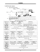
Page 41: ...ypass OL Bypass Relay open and Fault relay closed Auto Retransfer No Inverter OL Yes if bypass ok Bypass OL No Protection Item Low Battery Voltage level 1 Low Battery Voltage level 2 Inverter Output Current Limit LCD Message Line 4 will read BATTERY LOW DC UNDERVOLTAGE OUTPUT OVERLOAD Cause Battery Discharge Battery Shutdown Level reached Load Inrush current Operation Mode after Fault Battery Disc...

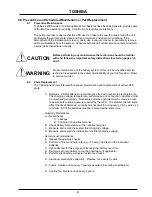
Page 42: ...iodic maintenance and replacement of certain UPS parts 1 Batteries VRLA batteries are maintenance free with respect to electrolyte only The charging voltage temperature performance and connection resistance must be monitored periodically Necessary corrective actions must be made in order to assure safe reliable power is supplied by the UPS The aforementioned items affect the life of batteries so r...

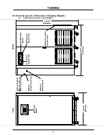
Page 43: ...mensions 75 and 100kVA Stop Run Key Switch 62 797 1595mm EPO Switch Section 6 6 Front Panel Section 6 5 Remote Contacts IBM AS 400 Male Connector RS232 C Female Connector 50 233 1275mm 32 308 820mm UPS Input MCCB Battery Connector Access Panel FRONT SIDE Optional Remote Eye II ...

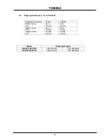
Page 44: ...pping Dimensions 75Kva 100kVA Width Inches cm 64 0 162 6 64 0 162 6 Depth Inches cm 42 5 108 0 42 5 108 0 Height Inches cm 72 438 184 0 72 438 184 0 Model Shipping Weights U42B3F10KC6CB 2600 Pounds 1180 Kilograms U42B3F750C6CB 2600 Pounds 1180 Kilograms ...

Page 45: ...TOSHIBA 44 TOSHIBA TOSHIBA INTERNATIONAL CORPORATION INDUSTRIAL DIVISION 13131 West Little York Road Houston Texas 77041 Tel 713 466 0277 Fax 713 466 8773 Printed in the U S A ...

Reviews: