24
4200FA Installation and Operation Manual
*
Remote Run
and
Remote Stop
must be enabled via the front panel. Once remote mode is enabled, the key switch on the front
panel is rendered inoperable until remote mode is disabled via the front panel.
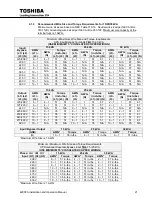
4.2.1
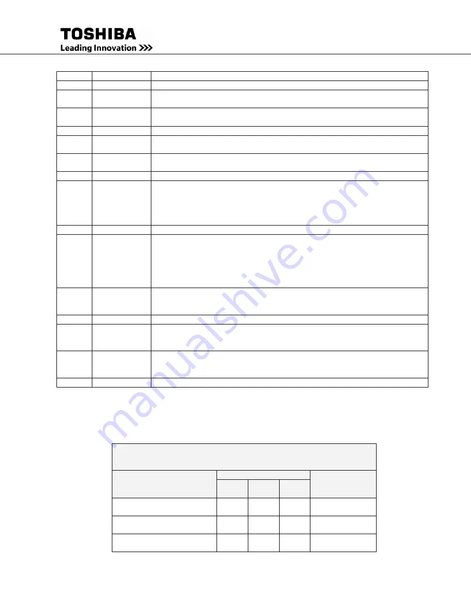
Recommended Wire Size and Torque Requirements
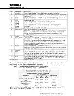
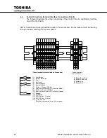
UPS Control and Battery Interface 15/25/30 kVA
*Indicates Class 1 wiring methods are to be used. Maximum Wire Size for Control Circuits is 12
AWG. Maximum for Battery is 1 AWG.
No.
TERMINAL
FUNCTION
1
Low Batt
(Dry Contact)
Closed
when battery voltage drops below minimum.
2
Batt Discharge
(Dry Contact)
Closed
when the Internal/external batteries are discharging into
the DC Bus.
3
Fault
(Dry Contact)
Closed
when fault occurs. Generic fault warning, could mean
any of several things; DCOC (DC Over Current), DCUB (DC Unbalanced) etc.
4
N/C
(Not Connected)
5
Inverter
Supply
(Dry Contact)
Closed
when inverter is operating normally.
6
Inverter
Supply
(Dry Contact) Closed
when inverter is operating normally. (Duplicate
terminals)
7
P24A3
24 Vdc 1 A max. source for Remote Run.
8
Remote Run*
Apply 24V to switch UPS to Inverter Mode
NOTE: The connection to the remote run inputs on terminals 7 and 8 must be
a discrete dry contact and must not be connected to other powered circuits.
Connection to other powered circuits may result in unpredictable circuit
operation or failure.
9
P24A3
24 Vdc (P24A3)
10
Remote Stop*
Apply 24Vdc to switch UPS to Static Bypass. The UPS will transfer to bypass
as soon as the input and bypass power are in sync.
NOTE: The connection to the remote stop inputs on terminals 9 and 10 must
be a discrete dry contact and must not be connected to other powered
circuits. Connection to other powered circuits may result in unpredictable
circuit operation or failure.
11
Bypass
(Dry Contact)
Closed
when UPS is in Bypass.
NOTE: Even though Remote Stop may be triggered, the UPS is not in Bypass
until Terminal 11 closes.
12
Common
13
EPO
(Dry Contact)
Short
across 13 and 14 will shut down all power in the UPS
including bypass and battery backup, and will cause the Battery Shunt Trip to
open the external battery breaker.
14
EPO
(Dry Contact)
Short
across 13 and 14 will shut down all power in the UPS
including bypass and battery backup, and will cause the Battery Shunt Trip to
open the external battery breaker.
15 – 24 N/C
(Not Connected)
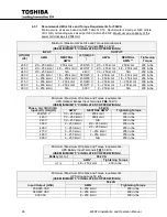
Minimum Wire Size and Torque Requirements
UPS Control and Battery Interface Circuits
USE MINIMUM 75 °C COPPER WIRING
TERMINAL
(TERMINAL #)
Wire Size AWG*
TIGHTENING
TORQUE
15
kVA
25
kVA
30
kVA
UPS CONTROL CIRCUITS
(1-24)*
14-16
14-16
14-16
8 in-lbs.
BATTERY CONTROL
CIRCUITS (3-6)*
14-16
14-16
14-16
8 in-lbs.
BATTERY
(+/-)
6 – 1
2 – 1
1
45 in-lbs.
Summary of Contents for 4200FA CT
Page 2: ...4200FA Installation and Operation Manual ...
Page 4: ...4200FA Installation and Operation Manual ...
Page 10: ...iv 4200FA Installation and Operation Manual This Page Intentionally Left Blank ...
Page 14: ...4 4200FA Installation and Operation Manual NOTE This Label for Battery Units Only ...
Page 85: ...4200FA Installation and Operation Manual 75 APPENDIX A Seismic Anchorages ...
Page 86: ...76 4200FA Installation and Operation Manual ...
Page 87: ...4200FA Installation and Operation Manual 77 ...
Page 88: ...78 4200FA Installation and Operation Manual ...
Page 96: ......
Page 97: ......


