4200FA Installation and Operation Manual
43
6.0 Operating the UPS
6.1
AC Input Mode (Normal Operation)
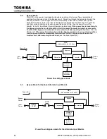
The following illustration shows circuit power flow when the UPS is operating normally in the AC Input
Mode. The converter of the UPS, including a boost chopper circuit, converts the AC input power into
DC power. The boost chopper circuit maintains a constant voltage and provides current limiting for
charging the batteries. It also supplies a DC voltage of the proper level to the inverter section. The
inverter section generates a high quality sine wave output voltage. The batteries are maintained in a
constantly charged state when the UPS is in the “Normal Operation Mode.”
Power flow in AC Input Mode
Converter
Inverter
Bypass
Charger/
Chopper
Isolating
XFMR
External
Batteries
Output
Power
MCCB
MBS
(Not available for LT units)
Input
Power
Power Flow
Summary of Contents for 4200FA CT
Page 2: ...4200FA Installation and Operation Manual ...
Page 4: ...4200FA Installation and Operation Manual ...
Page 10: ...iv 4200FA Installation and Operation Manual This Page Intentionally Left Blank ...
Page 14: ...4 4200FA Installation and Operation Manual NOTE This Label for Battery Units Only ...
Page 85: ...4200FA Installation and Operation Manual 75 APPENDIX A Seismic Anchorages ...
Page 86: ...76 4200FA Installation and Operation Manual ...
Page 87: ...4200FA Installation and Operation Manual 77 ...
Page 88: ...78 4200FA Installation and Operation Manual ...
Page 96: ......
Page 97: ......


