52
4200FA Installation and Operation Manual
Note:
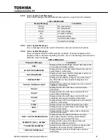
1) Line-4 will be blank when the BATT key is pressed during Battery Backup Mode
with normal battery voltage.
3) The # symbol signifies numerical values or other information supplied by the UPS.
6.13
Menu Tree
This is an overview of the menu tree for the LED display on the UPS detailed in the following
pages. The first item is the opening screen, subsequent screens can be reached sequentially by
successively pressing and holding the UP- DOWN arrow for approximately three seconds to progress to
the next screen.
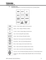
KEY:
LCD Display
MONI:
(No additional screens)
BATT:
(No additional screens)
INPUT:
INPUT VOLTAGE
BYPASS VOLTAGE
FREQ INPUT / BYPASS / SYNC OUTPUT
INPUT CURRENT
OUTPUT:
OUTPUT CURRENT
OUTPUT VOLTAGE LINE TO NEUTRAL / LINE TO LINE
FREQ INPUT / BYPASS / SYNC OUTPUT
INV OP POWER %/KW / INV OP PF
MENU:
CALENDER/CLOCK
BUZZER VOLUME
DISPLAY DURATION
RUN SWITCH SELECT (Local/Remote)
SERIAL COM STATION ADDR
OUTPUT VOLT. ADJUST
MENU DATA RESET
NOTE: Page through the menu screens by pressing the UP or Down arrow key for approximately 2-3 sec.
The top screen is the opening screen but the following screens can be accessed in sequential order in the
pattern 1-2-3-4-1-2 etc. or 1-4-3-2-1-4-3 etc.
6.14
Initial Battery Charge
The UPS Battery System must be charged before it is used for the first time or when the
unit has not been used (AC power source removed) for more than 10 days. Use the
following procedure to recharge the UPS Battery System:
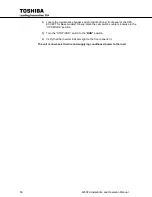
1) Switch on power at the UPS input distribution panel, and battery disconnects.
2) Move the UPS MCCB (Circuit Breaker 1) power switch on the inner front panel to
"on." The UPS battery charging circuit is now activated. The AC IN lamp will be
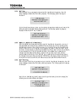
"on." The LCD screen should display the following message:
- UPS START UP -
> PLEASE WAIT
Summary of Contents for 4200FA CT
Page 2: ...4200FA Installation and Operation Manual ...
Page 4: ...4200FA Installation and Operation Manual ...
Page 10: ...iv 4200FA Installation and Operation Manual This Page Intentionally Left Blank ...
Page 14: ...4 4200FA Installation and Operation Manual NOTE This Label for Battery Units Only ...
Page 85: ...4200FA Installation and Operation Manual 75 APPENDIX A Seismic Anchorages ...
Page 86: ...76 4200FA Installation and Operation Manual ...
Page 87: ...4200FA Installation and Operation Manual 77 ...
Page 88: ...78 4200FA Installation and Operation Manual ...
Page 96: ......
Page 97: ......


