4200FA Installation and Operation Manual
55
the UPS and to any attached loads. All LED lamps are "off" and the LCD screen will
display the following message:
- OUTPUT SHUT DOWN -
OUTPUT VOLTAGE= 0 V
CURRENT=LOW/LOW/LOW%
6.17
Maintenance Bypass Procedure
NOTE: The 25-50kVA 4200 Base models do not come with an internal mechanical MBS.
Transferring to Maintenance Bypass will result in loss of power to the critical load unless
an external MPS is installed.
To safely set the unit in Maintenance Bypass, the UPS is first electrically switched to
bypass mode, and then mechanically switched to bypass mode. This prevents the UPS
from being placed in parallel with commercial power.
Follow the instructions below when switching the UPS to and from Maintenance Bypass
Mode.
WARNING
Failure to adhere to the following instructions could result in damage to your
equipment and/or you risk removal of power to any equipment attached to
the UPS.
6.17.1 Switch from UPS to Maintenance Bypass
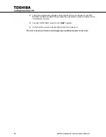
1) Turn the “STOP/RUN” key switch, located on the front panel, to “STOP." Operation
of the UPS inverter stops and the BYP LED illuminates. Output power is now
provided to the load through the Bypass circuit.
While in this mode, if a power
failure occurs on the commercial power source, the UPS will lose power.
Power to the critical load device will be interrupted.
The battery charging
circuit and chopper circuit remains active.
2) Verify that step one above is followed, and that the BYP LED indicator on the front
panel is illuminated.
3) Locate the maintenance bypass rotary cam switch (middle of inner front panel of
the UPS); slowly rotate the cam switch clockwise to the “BYPASS MODE” position.
(For the 25/50kVA 4200FA Base models, see Section 6.17 Note)
4) Turn off MCCB breaker labeled “MAIN POWER SWITCH."
The unit is now in the Maintenance Bypass mode and may be serviced. For units
with internal transformers, except the Base models, the transformers are still
energized.
6.17.2 Switch from Maintenance Bypass to UPS
1) Verify that the “STOP/RUN” switch is in the “
STOP”
position. Turn on MCCB
“MAIN POWER SWITCH."
2) Wait until the output fans turn on (this indicates that the unit is in the Bypass
mode), and that the BYP LED light on the front panel is lit.
3) For units with an external battery cabinet, turn on MCCB “BATTERY CABINET."
Summary of Contents for 4200FA CT
Page 2: ...4200FA Installation and Operation Manual ...
Page 4: ...4200FA Installation and Operation Manual ...
Page 10: ...iv 4200FA Installation and Operation Manual This Page Intentionally Left Blank ...
Page 14: ...4 4200FA Installation and Operation Manual NOTE This Label for Battery Units Only ...
Page 85: ...4200FA Installation and Operation Manual 75 APPENDIX A Seismic Anchorages ...
Page 86: ...76 4200FA Installation and Operation Manual ...
Page 87: ...4200FA Installation and Operation Manual 77 ...
Page 88: ...78 4200FA Installation and Operation Manual ...
Page 96: ......
Page 97: ......


