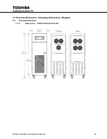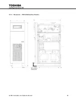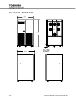
90
4200FA Installation and Operation Manual
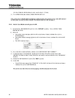
With the key switch in the “BYPASS” position the LED’s will show (Ref. Table 9.1):
LED
Light
On-Line/Fault
(Off)
Warning
Flashing
A/C Input
Steady Green
The UPS battery charging circuit is now activated. Move the “BYPASS/RUN” key switch to the “RUN”
position. The inverter will start and the UPS will transfer to the Normal Operating Mode.
LED
Light
On-Line/Fault
Steady Green
Warning
(Off)
A/C Input
Steady Green
If a fault occurs during start-up, the touchscreen footer Faults (Left side of the footer) will display the fault
code, and the display LED’s will show:
LED
Light
On-Line/Fault
Steady Red
Warning
(Off)
A/C Input
Steady Green
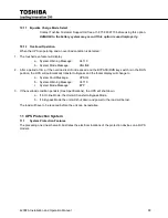
Shutdown Procedure
10.8
Use the following shutdown procedure when turning off the UPS.
1. Rotate the “BYPASS/RUN” key switch to “BYPASS."
2. Operation of the inverter halts. Output power is now provided to the load through the unit's
Bypass circuit.
While in this state of operation; if a power failure occurs in the commercial power source, the UPS
will lose power. Power to the critical load device will be interrupted.
The battery charging circuit and chopper circuit remains active.
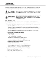
DANGER
Do not touch the UPS terminals even though the operation switch has
been moved to the STOP position. The UPS may be supplying power
through the Bypass circuit.
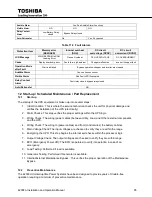
3. The LED’s display as follows::
LED
Light
On-Line/Fault
(Off)
Warning
Flashing
A/C Input
Steady Green
4. Switch the Circuit Breaker to the "off" position.
Power is removed from the UPS and to any
attached loads
. All LED’s are "off" and the touchscreen goes blank.
5. When the EPO (Emergency Power Off) switch, located on the front panel (or from a remote
located EPO switch) is pushed, the Circuit Breaker is tripped and power is removed from the UPS
and to any attached loads. All LED’s are "off" and the touchscreen goes blank.
Summary of Contents for 4200FA Series
Page 2: ...4200FA Installation and Operation Manual ...
Page 12: ...vi 4200FA Installation and Operation Manual ...
Page 16: ...4 4200FA Installation and Operation Manual NOTE This Label for Battery Units Only ...
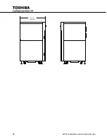
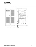
Page 110: ...98 4200FA Installation and Operation Manual 36 3 in 922 mm ...
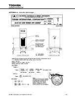
Page 115: ...4200FA Installation and Operation Manual 103 APPENDIX A Seismic Anchorages ...
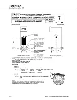
Page 116: ...104 4200FA Installation and Operation Manual ...
Page 117: ...4200FA Installation and Operation Manual 105 ...
Page 118: ...106 4200FA Installation and Operation Manual ...
Page 136: ...124 4200FA Installation and Operation Manual ...
Page 137: ......

