4200FA Installation and Operation Manual
63
9
Operator Interface
Front Panel Display Layout
9.1
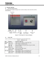
The 4200FA UPS front panel is equipped with a Touchscreen display, three status LEDs, and three
manual switches.
Display LEDs
9.2
Table 9.1 describes the front panel LED behaviors and the associated meaning.
Table 9.1 LED Behavior Key
LED
Behavior
Significance/Meaning
On-Line/
Fault
Green - ON
UPS is in On-Line, Backup, or Battery Test mode.
Green - OFF
UPS in Bypass of Shutdown mode.
Red - ON
One or more faults occurred. See
Records: Faults
for details.
Red - OFF
No fault occurred.
Warning
Amber - ON
Service Call needed.
Amber - Flashing
One or more Warnings occurred.
Amber - OFF
No Warning occurred.
A/C Input
Green - ON
Input or Bypass voltage is within specified range.
Green - Flashing
Input or Bypass voltage is over specified range.
Green - OFF
Input or Bypass voltage is under specified range.
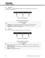
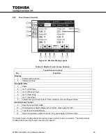
Touch Screen
Display
Indicators
On-Line /Fault
Warning
ACInput
Display
Reset
Button
EPO (Emergency
Power Off Switch)
Bypass/On-Line
Switch
Figure 9-1 Panel Layout for Touchscreen Display
Summary of Contents for 4200FA Series
Page 2: ...4200FA Installation and Operation Manual ...
Page 12: ...vi 4200FA Installation and Operation Manual ...
Page 16: ...4 4200FA Installation and Operation Manual NOTE This Label for Battery Units Only ...
Page 110: ...98 4200FA Installation and Operation Manual 36 3 in 922 mm ...
Page 115: ...4200FA Installation and Operation Manual 103 APPENDIX A Seismic Anchorages ...
Page 116: ...104 4200FA Installation and Operation Manual ...
Page 117: ...4200FA Installation and Operation Manual 105 ...
Page 118: ...106 4200FA Installation and Operation Manual ...
Page 136: ...124 4200FA Installation and Operation Manual ...
Page 137: ......


