86
4200FA Installation and Operation Manual
10 UPS Operation
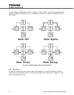
The 4200FA UPS is hardwired to both utility power and the critical loads. The two main operating states
are
•
On-Line with the UPS providing clean power to the load.
•
Bypass, where the power is routed around the converter-inverter of the UPS and fed directly to
the load.
•
A Third state, Emergency shut-down, is for emergency use only and is discussed separately.
The UPS can be switched between On-Line and Bypass by switching the key switch located below the
touchscreen display.
Initial UPS Startup
10.1
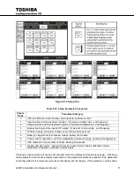
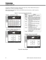
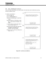
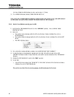
The first time the UPS is started after installation, use the touchscreen to enter the current time and date.
1) Start the UPS as described in
Section 10.2,
steps 1-5.
2) Enter the
System Date
:
i)
Press the
Setup
tab.
ii) Press
System Date
in the Data Display Area.
iii)
Enter the date in the following format:
Www
Mmm DD YYYY
(a)
Www
is the three character day of the week: Mon, Tue, Wed...
(b)
Mmm
is the three character Month: Jan, Feb, Mar...
(c)
DD
is the two digit day of the month: 01, 12, 30...
(d)
YYYY
is the four digit year: 2013
iv) Press
Write
to store the date.
v) Press
Quit
to exit
System Date
setup.
3) Enter the
System Time
:
Press the
Setup
tab.
i)
Press
System Time
in the Data Display Area.
ii)
Enter the Time in the following format:
HH:MM AM
(a)
HH
is the two digit hour followed by a colin (:)
(b)
MM
is the two digit month.
(c)
AM/PM
is before or after noon.
iii) Press
Write
to set the time.
iv) Press Quit to exit System Time setup.
Starting the UPS
10.2
1. Switch the main circuit breaker (MCCB) on the inside front of the UPS to the
ON
position.
2. Switch on the optional second Circuit Breaker if the UPS is equipped with dual inputs. The breaker(s)
should normally remain in the
ON
position.
Summary of Contents for 4200FA Series
Page 2: ...4200FA Installation and Operation Manual ...
Page 12: ...vi 4200FA Installation and Operation Manual ...
Page 16: ...4 4200FA Installation and Operation Manual NOTE This Label for Battery Units Only ...
Page 110: ...98 4200FA Installation and Operation Manual 36 3 in 922 mm ...
Page 115: ...4200FA Installation and Operation Manual 103 APPENDIX A Seismic Anchorages ...
Page 116: ...104 4200FA Installation and Operation Manual ...
Page 117: ...4200FA Installation and Operation Manual 105 ...
Page 118: ...106 4200FA Installation and Operation Manual ...
Page 136: ...124 4200FA Installation and Operation Manual ...
Page 137: ......

