4200FA Installation and Operation Manual
87
3. Verify that the
On-Line
LED on the front panel lights green. All LED’s on the front panel may light for
a moment when the input breaker is turned on. This is normal. The UPS will now be supplying power
in the bypass mode.
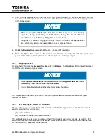
When running the UPS for the first time or after the power failure backup
operation, charge the battery cabinet batteries, if any, for at least 24 hours
(input breaker on) before operating the connected load.
Using the UPS without charging the battery shortens the battery backup operation
time, which may result in the loss of data in case of a power failure.
4. Rotate the
Bypass/On-Line
switch
to
On-Line
to begin UPS operation.
5. Press the
Quick View
button on the Quick Access Toolbar and verify the UPS has input/output
power. If the UPS has backup batteries, verify the batteries are being charged.
Stopping the UPS
10.3
To stop the UPS, rotate the
Bypass/On-Line
switch to
Bypass
. The
On-Line
LED changes from green
to off. The UPS is now in Bypass mode.
If the input breaker is turned off while UPS is in the bypass state, the output
power stops. Any load devices will lose power.
Ensure that all sensitive loads have been previously shut down.
To completely stop the UPS, open/turn off the main input breaker MCCB, and the secondary Input
breaker if available.
EPO (Emergency Power Off) Function
10.4
These units are equipped with terminals for receiving an EPO (Emergency Power Off) "closed contact"
switch command from two locations:
(1) A remote location
(2) From the front panel mounted EPO switch.
This safety feature enables quick shutdown of the UPS AC output and battery circuits. Usually the EPO
switch is installed in a central location that is easily accessible to personnel concerned with the operation
of the UPS and the equipment connected to it.
Summary of Contents for 4200FA Series
Page 2: ...4200FA Installation and Operation Manual ...
Page 12: ...vi 4200FA Installation and Operation Manual ...
Page 16: ...4 4200FA Installation and Operation Manual NOTE This Label for Battery Units Only ...
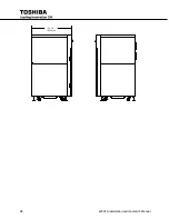
Page 110: ...98 4200FA Installation and Operation Manual 36 3 in 922 mm ...
Page 115: ...4200FA Installation and Operation Manual 103 APPENDIX A Seismic Anchorages ...
Page 116: ...104 4200FA Installation and Operation Manual ...
Page 117: ...4200FA Installation and Operation Manual 105 ...
Page 118: ...106 4200FA Installation and Operation Manual ...
Page 136: ...124 4200FA Installation and Operation Manual ...
Page 137: ......

