background image


4200FA XT 80kVA Installation and Operation Manual 

53 

7.0  UPS Protection System 

7.1 

System Protection Features 

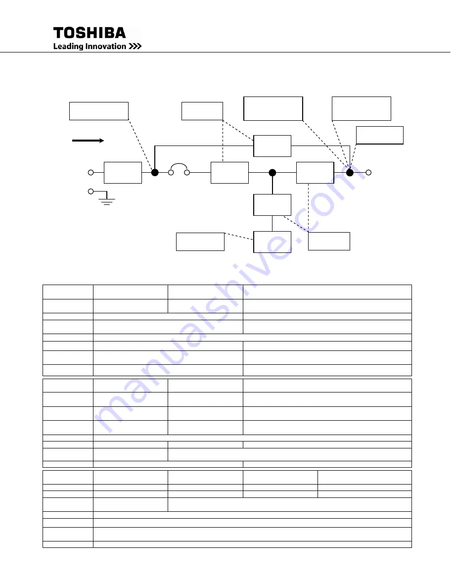
The following one-line schematic illustrates the electrical locations of the protection devices 
on the 80 kVA UPS models.  


7.2 

System Protection Functions 

The following tables show the built-in UPS fault-protection functions of the 80 kVA models. 

Built-in UPS Fault Protection Functions 

Protection Item 

Inverter Overvoltage 

(IVOV) 

Inverter Undervoltage 

(IVUV) 

UPS Overload 

LCD Message 

INVERTER 

OVERVOLTAGE 

INVERTER 

UNDERVOLTAGE 

OUTPUT OVERLOAD 

Cause 

Control Malfunction;  Feedback Error 

Overload or short circuit at the load. 

Operation Mode 

after Fault 

Bypass Operation; Chopper and Inverter Stopped 

 Inverter Overload: Transfer to bypass; Inverter stopped. 
 Bypass Overload: Inverter, Chopper, & Bypass stopped. 

Audible Alarm 

Yes: See Section 6.7 Audible Alarm Functions 

Visible Alarm 

Red Fault Lamp On 

Inverter OL: No Fault Lamp — Bypass OL: Fault Lamp On  

Relay Contact 

Alarm 

Fault Relay closed; Bypass Relay closed 

Inverter OL: Bypass Relay closed 

Bypass OL: Bypass Relay open and Fault relay closed 

Auto-Retransfer 

No 

Inverter OL: Yes, if bypass OK — Bypass OL: No 


Protection Item 

Low Battery Voltage 

(level-1) 

Low Battery Voltage 

(level-2) 

Inverter Output Current Limit 

LCD Message 

Line-4 will read 

BATTERY LOW 

DC UNDERVOLTAGE 

OUTPUT OVERLOAD 

Cause 

Battery Discharge 

Battery Shutdown Level 

reached 

Load Inrush current 

Operation Mode 

after Fault 

Battery Discharge 

Shutdown: No Output 

If Bypass OK, transfer to bypass 

If not, current-limit mode 

Audible Alarm 

Yes: See Section 6.7 Audible Alarm Functions 

Visible Alarm 

Battery Lamp Flickers 

NO 

NO 

Relay Contact 

Alarm 

Low Battery Relay closed 

Bypass Relay closed 

Auto-Retransfer 

No 

Yes, if bypass OK 


Protection Item 

Memory error (EERR) 

Internal overheat (OH) 

DC circuit overvoltage 

(DCOV) 

DC circuit overcurrent (DCOC) 

LCD Message 

MAIN EEPROM ERROR 

OVERHEAT; INTERNAL 

DC OVERVOLTAGE 

DC OVERCURRENT 

Cause 

Control board chip error 

Fan failure; high ambient 

Chopper malfunction 

Inverter / chopper fault 

Operation Mode 

after Fault 

Start is inhibited 

Bypass operation; chopper and inverter are stopped 

Audible Alarm 

Yes; continuous buzzer 

Visible Alarm 

RED fault lamp On 

Relay Contact 

Alarm 

Fault relay closed; bypass relay closed 

Auto-Retransfer 

NO 

Converter


Inverter


Static 

Bypass


Charger/ 
Chopper


Isolating 

XFMR


External 

Batteries


Output 

Power 

Input 

Power 

MCCB


Power Flow


Overcurrent 

Input Abnormal 

Current-Limit 
Overload 

Over-Voltage / 
Under-Voltage


Overhea

Low Battery 

Overhea

Summary of Contents for 4200FA XT

Page 1: ...1 UNINTERRUPTIBLE POWER SYSTEM UPS 4200FA XT INSTALLATION AND OPERATION MANUAL Three Phase 80 kVA UPS Document No 56418 007 Date May 2013 ...

Page 2: ...4200FA XT 80kVA Installation and Operation Manual ...

Page 3: ...T THREE PHASE 80 kVA UNINTERRUPTIBLE POWER SYSTEM USER S MANUAL FOR MODELS T42F3F800FAXXN T42F3 800FAXXN T42 3F800FAXXN Document No 56418 007 Date May 2013 TOSHIBA INTERNATIONAL CORPORATION INDUSTRIAL DIVISION 13131 West Little York Road Houston TX 77041 9990 ...

Page 4: ...4200FA XT 80kVA Installation and Operation Manual ...

Page 5: ...sting warranty Any Electrical or mechanical modifications to this equipment without prior written consent of the TOSHIBA will void all warranties and may void UL CUL listing Unauthorized modifications may also result in equipment damage personal injury or loss of life IMPORTANT NOTICE UNINTERRUPTIBLE POWER SYSTEM If additional information or technical assistance is required call TOSHIBA Customer S...

Page 6: ...l other product or trade references appearing in this manual are registered trademarks of their respective owners TOSHIBA shall not be liable for technical or editorial omissions or mistakes in this manual Nor shall it be liable for incidental or consequential damages resulting from the use of information contained in this manual This manual is copyrighted No part of this manual may be photocopied...

Page 7: ... and External Battery Interface Connections 24 4 1 5 Recommended Wire Size and Tightening Torque UPS Control and Battery Interface 24 4 2 Communication Interface 25 4 2 1 Remote Contact 25 4 2 2 RS 232C 26 4 2 3 UPS Shutdown via RS 232C 26 5 0 Specifications 27 5 1 Specifications 4200FA 80kVA without Internal Transformer 27 5 2 Specifications 4200FA 80kVA with Internal Transformer 28 5 3 Specifica...

Page 8: ...ng Buzzer Volume 46 6 15 3 Settings for Display Duration 47 6 15 4 Run Switch Select 47 6 15 5 Serial Com Station Address 48 6 15 6 Output Voltage Adjustment 48 6 15 7 Equalize Charge Mode Select 49 6 15 8 Reset to Default Settings 49 6 16 Overload Operation 50 6 17 Backup History Fault History 51 7 0 UPS Protection System 53 7 1 System Protection Features 53 7 2 System Protection Functions 53 8 0...

Page 9: ...on symbol is an exclamation mark enclosed in a triangle which precedes the word CAUTION The Caution warning symbol is used to indicate situations and conditions that can cause operator injury and or equipment damage CAUTION 3 Attention warning The attention warning symbol is an exclamation mark enclosed in a triangle which precedes the word ATTENTION The Attention warning symbol is used to indicat...

Page 10: ... labels that may be found attached to the equipment DO NOT remove or cover any of the labels If the labels are damaged or if additional labels are required contact your TOSHIBA representative for additional labels The following are examples of the warning labels that may be found on the equipment The labels are there to provide useful information or to indicate an imminently hazardous situation th...

Page 11: ...onductor sizing must be installed for safe operation During operation keep all covers in place and cabinet doors shut When performing visual inspections and maintenance if possible be sure the UPS is turned off and the incoming AC feed is turned off and locked out If it is necessary to make measurements with the power on do not touch any electrical connection points Remove all jewelry from wrists ...

Page 12: ...all power sources Wait at least five 5 minutes for power to dissipate then check voltage before servicing Capacitors stay charged after power has been shut off Accidental contact with live parts can cause personal injury and death RISK OF ELECTRIC SHOCK 39561 For Battery Units Only ...

Page 13: ...ills and knowledge relating to the construction installation operation and maintenance of this electrical equipment and has received safety training on the hazards involved Refer to the latest edition of NFPA 70E for additional safety requirements Qualified Personnel Shall 1 Have carefully read the entire operation manual 2 Be trained and authorized to safely energize de energize ground lockout ta...

Page 14: ...connected from the power source 2 Remove watches rings jewelry or other metal objects 3 Use tools with insulated handles to prevent inadvertent shorts 4 Wear rubber gloves and boots 5 Do not place tools or metal parts on top of the batteries 6 Determine if the battery is inadvertently grounded If inadvertently grounded remove source of ground Contact with any part of a grounded battery can result ...

Page 15: ...ITÉ CONSERVER CES INSTRUCTIONS Cette notice contient des instructions importantes concernant la sécurté ATTENTION Un batterie puet présenter un risque de choc électrique de brûlure par transfert d énergie ATTENTION L élimination des batteries est règlementèe Consultar les codes locaux à cet effet ...

Page 16: ...cation and use The TOSHIBA 4200FA Uninterruptible Power Systems UPS provide continuous computer grade AC power in a compact and efficient high performance unit The UPS assures safe reliable operation of critical office equipment ranging from personal computers to mini computers to local area networks LAN All units feature an audible alarm that sounds if the battery voltage drops below standard dur...

Page 17: ... the shipping crate panels to each other and to the pallet Remove the crate and foam packing material 3 Unbolt the unit from the shipping pallet 4 Lift the UPS from the pallet using a forklift that has sufficient capacity Approach the UPS only from the front or rear CAUTION Do not attempt to move the unit by the sides Only move the unit with a forklift or pallet jack Moving the unit by pushing on ...

Page 18: ... Allow the UPS to be operated for 24 hours to ensure that the batteries are fully charged 2 Stop the unit see Shutdown Procedure in section 6 12 3 Place the MCCB switch of the UPS in the OFF position see section 4 1 for location Storing 1 Store within the temperature range of 4 104 F 20 40 C 2 For best results store the UPS in the original shipping container and place on a wood or metal pallet 3 T...

Page 19: ...operating temperature for maximum battery life 4 Do not install the UPS in a location that is subject to high humidity 5 Do not allow the UPS to be exposed to direct sunlight 6 Do not install the UPS in areas that are subject to contamination such as high levels of airborne dust metal particles or flammable gasses 7 Avoid installation near sources of electrical noise and always ensure that the ear...

Page 20: ...arting current or a long starting time such as vacuum cleaners or machine tools over sizing for locked rotor current required 5 Do not insert metal objects or combustible materials in the ventilation slots of the UPS 6 Do not place hang or paste any objects on the top or on the exterior surfaces of the UPS 7 The capacitors of the UPS maintain a residual charge for a while after turning off the UPS...

Page 21: ...S has been fully discharged The UPS could be damaged if the unit is not fully powered down before the breaker is reset 4 0 UPS Connections 4 1 UPS Power and Control Connections The following illustration shows the wiring connections to the input and output termination points and the Control Circuit Terminal Blocks for the 4200FA 80 kVA UPS ...

Page 22: ...N A 375 480 VAC 1 0 AWG to 500 MCM N A 375 Output AWG L1 L2 L3 AWG OUTN Tightening Torque in lbs 208 V 120 VAC 500 MCM 2 x 350 400 MCM 375 Input 500 Neutral Battery Circuit AWG POS NEG Tightening Torque in lbs 288 VDC Nominal 400 MCM to 2 x 3 0 400 MCM 500 Input Output Ground AWG GND Tightening Torque in lbs 2 AWG minimum see note 1 see note 2 All wire sizes are per NEC Use copper wiring with at l...

Page 23: ... cable should be run inside of the conduit with the input power output power and control circuits 3 Always ground the unit to prevent electrical shock and to help reduce electrical noise 4 Follow wire size and tightening torque recommendations provided in this manual CAUTION THE METAL OF A CONDUIT IS NOT AN ACCEPTABLE GROUND Single Input UPS with input transformer Shown with bottom cable entry con...

Page 24: ...16 4200FA XT 80kVA Installation and Operation Manual Dual Input UPS with input transformer Shown with bottom cable entry configuration ...

Page 25: ...4200FA XT 80kVA Installation and Operation Manual 17 Single Input UPS with no transformers Shown with bottom cable entry configuration ...

Page 26: ...18 4200FA XT 80kVA Installation and Operation Manual Dual Input UPS with no transformers Shown with bottom cable entry configuration ...

Page 27: ...4200FA XT 80kVA Installation and Operation Manual 19 Single Input UPS with input transformer Shown with top cable entry configuration ...

Page 28: ...20 4200FA XT 80kVA Installation and Operation Manual Dual Input UPS with input transformer Shown with top cable entry configuration ...

Page 29: ...4200FA XT 80kVA Installation and Operation Manual 21 Single Input UPS with no transformers Shown with top cable entry configuration ...

Page 30: ...22 4200FA XT 80kVA Installation and Operation Manual Dual Input UPS with no transformers Shown with top cable entry configuration ...

Page 31: ...figuration For those requiring a dual input configuration see below This change should only be performed by factory trained service personnel and not by the end user Single Input Configuration Dual Input Configuration Bypass jumpers are factory installed on bypass bus bars Move wires from bypass bus bars to stand offs to configure for dual input ...

Page 32: ...Discharge 3 Fault 4 Not Used 5 Inverter Supply 6 Inverter Supply 7 Remote Run P24A3 8 Remote Run 9 Remote Stop P24A3 10 Remote Stop 11 Bypass 12 Common 13 EPO 14 EPO TB3 Connections 3 Battery Shunt Trip Out 4 Battery Shunt Trip Out 5 Battery AUX In 6 Battery AUX In 4 1 5 Recommended Wire Size and Tightening Torque UPS Control and Battery Interface Minimum Wire Size and Tightening Torque for UPS Co...

Page 33: ...on The following schematic shows the contact state and pin assignment for each signal and the associated DB9 connector pin out Notes 1 Switches are shown in their inactive states if battery voltage is low pin 7 will be connected to System Common 2 Contacts are resistive loads rated at 30 VDC 0 1 A 125 VAC 3 A 3 Pin 3 is not used 5 System Common 6 Bypass Active Fault Signal Detect 1 2 8 UPS On line...

Page 34: ...rred or Not Occurred DC Bus Over Current DC Bus Over Voltage DC Bus Under Voltage Input Over Current Overheat Overload Being Timed Overload allowable time exceeded Output Over Voltage during Normal Mode Output Under Voltage during Normal Mode The connector pin assignment and female connector outline are illustrated below 4 2 3 UPS Shutdown via RS 232C When the UPS is operating from its internal ba...

Page 35: ...ency Regulation 0 1 in free running mode Frequency Synchronous Operation Range 5 1 0 1 5 Hz 1 0 Hz std switch selectable by qualified technician dip switch sets Slew Rate and Synch Range simultaneously Frequency Slew Rate Voltage Transients Recovery time 50 ms 3 100 load step change 5 loss or return of input voltage 3 transfer of bypass to inverter Inverter Overload Capacity 125 30 sec 150 5 sec B...

Page 36: ...60 Hz Frequency Regulation 0 1 in free running mode Frequency Synchronous Operation Range 5 1 0 1 5 Hz 1 0 Hz std switch selectable by qualified technician Frequency Slew Rate 1 Hz s to 3 Hz s Voltage Transients Recovery time 50 ms 3 100 load step change 5 loss or return of input voltage 3 transfer of bypass to inverter Inverter Overload Capacity 125 for 30 sec 150 for 5 sec Bypass Overload Capaci...

Page 37: ...Thermal Loss BTU Hr Transformerless W Internal Transformer 100 Load 29 778 34 374 75 Load 23 184 26 662 50 Load 16 750 19 117 25 Load 11 984 13 225 No Load 5 398 8 319 The thermal loss are listed for no load 25 50 75 100 loads under two sets of conditions UPS without internal transformer UPS with Internal transformer NOTE The thermal values listed are representative only Individual performance may...

Page 38: ...the main circuit of the UPS to the Bypass circuit Power flow through the Bypass is shown in the following illustration This changeover occurs automatically in less than 4 milliseconds The switching period is not long enough to cause interruptions to occur in most loads If the power flow is transferred to the bypass circuit because of an overload and the overload condition ends within a specified p...

Page 39: ...minimum V min The rated battery voltage table on page 36 shows V min The battery backup time and discharge process is explained in Section 6 2 Power flow in battery backup mode for the 4200FA 80 kVA UPS 6 1 4 External Maintenance Bypass Customer Supplied An external maintenance bypass may be installed in parallel with the UPS to allow servicing of the UPS while maintaining power to the load Contac...

Page 40: ...nd type of load temperature and other variables CAUTION Contact your TOSHIBA sales representative if using battery systems other than TOSHIBA designed battery systems to determine compliance Using other systems may void the warranty and or the safety certifications The following illustration shows the battery discharge process at full load conditions 6 3 Battery Low Voltage Tolerances Excessive di...

Page 41: ...and long battery life In the second period constant voltage control starts and the current gradually decreases as the batteries charge to the fully charged state In the third period a trickle current continues to flow into the batteries to maintain the fully charged status at the normal DC Voltage level A full recharge requires approximately 24 hours 90 recharge in 10 X discharge time after a comp...

Page 42: ...Operation P N 67667 Panel Layout for 4 Line LCD Panel Display see Section 6 9 6 22 in this Manual RESET MENU ENTER INPUT OUTPUT MONI BATT F1 BUZZ STOP BATT TEST EPO RUN STOP UPS ON LINE 4200FA UNINTERUPTIBLE POWER SYSTEM AC IN INV BYP BATT FAULT 4 line liquid crystal display screen see Section 6 9 Line 1 Line 2 Line 3 Line 4 Emergency Power Off switch see Section 6 6 RUN STOP key switch Green ligh...

Page 43: ... input mode see Section 6 1 1 battery backup mode see Section 6 1 3 or the circuit bypass mode see Section 6 1 2 See EMERGENCY OFF screen in Section 6 12 Shutdown Procedure The following figure shows the UPS condition after application of the EPO switch Use the Start up Procedure see Section 6 11 for restarting the unit 6 7 Audible Alarm Functions While in the battery backup mode during a fault du...

Page 44: ...2 second on and 1 2 second off The BATT LED will go off if the battery voltage reaches the shutdown level during the battery discharge mode On when the UPS is experiencing a fault 6 8 1 LED System Status The following table shows the UPS system status that can be determined by decoding the on and off condition of the LED lamps It should be used in conjunction with the LCD display see Section 6 9 a...

Page 45: ...scription UPS START UP Displayed when UPS is in the start up condition or display board is resetting BYPASS OPERATION Displayed when the UPS is in Bypass Operation UPS ON LINE Displayed when the inverter is running BATTERY DISCHARGE Displayed during Utility abnormality inverter is supplying power from batteries Unit shuts down after Vmin is reached OUTPUT SHUTDOWN Displayed during power failure if...

Page 46: ...the UPS has an internal DC bus unbalance referenced to Neutral abnormal UPS OL Displayed when UPS has tripped due to an overload condition abnormal INOV Displayed when inverter output over voltage has occurred abnormal INUV Displayed when inverter output under voltage has occurred abnormal BATTOH OR MCCB B OPEN Displayed when the optional battery over temp sensor has annunciated or if the external...

Page 47: ... 3 With the key switch in the STOP position the AC IN and the BYP lamp will be on and the LCD display will show the following message BYPASS OPERATION OUTPUT VOLTAGE 208V CURRENT 100 100 100 DATE DAY TIME 4 Turn the Key Switch to RUN and the UPS performs the Automatic Battery Test The Automatic Battery Test is performed only when the software is enabled for this function The default setting is Dis...

Page 48: ... and the LCD display will show the following message BYPASS OPERATION OUTPUT VOLTAGE 208V CURRENT 100 100 100 DATE DAY TIME The battery charging circuit of the UPS is now activated Move the RUN STOP key switch to the RUN position The inverter of the UPS will start and the UPS will be in the normal operating mode Both the AC IN and the INV LEDs will be on The following system message is an example ...

Page 49: ...STOP position The UPS may be supplying power through the bypass circuit The LCD display shows the following message when in the Bypass operating mode BYPASS OPERATION OUTPUT VOLTAGE 208V CURRENT 100 100 100 DATE DAY TIME Move the MCCB power switch to Off Power is removed from the UPS and to any attached loads All lamps are off and the LCD display shows the following message so long as there is suf...

Page 50: ...ditions see Section 6 14 2 OUT Output Press to display UPS output conditions see section 6 14 3 BATT TEST Battery Test Press to execute on line battery test see section 6 14 6 BUZZ STOP Buzzer Off Press to stop the audible alert buzzer see section 6 14 7 MENU Menu Press to display the main menu see section 6 14 5 ENTER Enter Press to accept a user selected command or action see section 6 14 5 RESE...

Page 51: ...n AC input power failure occurs and no abnormal operating conditions are present the UPS switches to standard Battery Backup mode The following system message is displayed BATTERY BACKUP OUTPUT VOLTAGE 208V CURRENT 100 100 100 DATE DAY TIME 6 14 2 IN Pressing the IN key during normal AC Input mode of operation displays input voltage information The following system message is displayed UPS ON LINE...

Page 52: ...een for that menu item Press the Up Down arrow keys to move the display to the next From the adjustment screen if the MENU key is pressed any changes are discarded and the display returns to the regular menu screen with the previous data values shown If the ENTER key is pressed from the adjustment screen the changes are saved After pressing ENTER the display screen will return to the regular menu ...

Page 53: ... is inhibited for 20 min Only one battery test can be done approximately every 20 min 6 14 7 BUZZ STOP Key Turns off the audible alarm 6 14 8 RESET Key Resets the LCD display board software should a system lock up occur The reset does not reset memory variables Use of the RESET function is very important when a fatal communication error has occurred Press and hold the RESET key for five seconds or...

Page 54: ...st the character s above the flashing cursor Press the ENTER key to advance the cursor 6 15 2 Adjusting Buzzer Volume Press the MENU key to access the menu data screens and press the Down arrow key to access the Buzzer Volume adjustment screen BUZZER VOLUME ADJUST LOUD MEDIUM SOFT F1 DATA SET MODE PRV NEXT SCREEN Press the F1 key to display the following active adjustment screen BUZZER VOLUME ADJU...

Page 55: ...menu and discard the change Under any of the following conditions the LCD will remain on continuously without regard to the Display Duration setting 1 The UPS has received an emergency off command 2 The UPS is in battery discharge mode 3 A fault has been detected in the main unit 4 The UPS is in an overload condition 6 15 4 Run Switch Select Press the MENU key to access the menu data screens Press...

Page 56: ...ode press the MENU key for 4 seconds or more to display the output voltage adjustment screen OUTPUT VOLT ADJUST OUTPUT VOLTAGE F1 DATA SET MODE PRV NEXT SCREEN Press the F1 key to display the following active adjustment screen OUTPUT VOLT ADJUST REFERENCE ADJUST CHANGE DATA ENTER ACCEPT CHANGE The fields marked will show the numerical value of the allowable voltage adjustment parameter values Pres...

Page 57: ...e original factory default settings adjustment screen MENU DATA RESET DATA INITIALIZATION F1 TO ACCESS RESET PRV NEXT SCREEN Press the F1 key to display the following active adjustment screen MENU DATA RESET DATA INITIALIZATION MENU NO DATA RESET ENTER ACCEPT CHANGE When the ENTER key is pressed the following factory defaults are reset 1 Reset the voltage reference setting to 0 2 Reset the buzzer ...

Page 58: ...resent the following screen will be displayed BYPASS OPERATION OUTPUT VOLTAGE 208 CURRENT 114 116 114 DATE DAY TIME After the load is reduced and if the RUN STOP key switch is in the RUN position the UPS will return to the Inverter mode of operation after a period of time During the wait time the following screen will be displayed BYPASS OPERATION OUTPUT VOLTAGE 208V CURRENT 100 100 100 PLEASE WAI...

Page 59: ...t screen to be displayed BATT DISCHARGE COUNT TIMES F1 FOR DETAILS TO SCROLL Press the F1 key to display the record relating to the first discharge event BACKUP HISTORY 1 MIN SEC VB 324V BT PF OL EXIT F1 NEXT Press the F1 key again to display the record relating to each subsequent discharge event BACKUP HISTORY MIN SEC VB 324V BT PF OL EXIT F1 NEXT Press the Up Down arrow keys to return to the Bat...

Page 60: ...the first fault FAULT HISTORY 1 Date Time fault code EXIT F1 NEXT Press the F1 key again to display the record relating to each subsequent fault FAULT HISTORY Date Time fault code EXIT F1 NEXT Press the Up Down arrow keys to return to the Fault Count screen TOTAL FAULT COUNT TIMES F1 FOR DETAILS TO SCROLL ...

Page 61: ...OL No Protection Item Low Battery Voltage level 1 Low Battery Voltage level 2 Inverter Output Current Limit LCD Message Line 4 will read BATTERY LOW DC UNDERVOLTAGE OUTPUT OVERLOAD Cause Battery Discharge Battery Shutdown Level reached Load Inrush current Operation Mode after Fault Battery Discharge Shutdown No Output If Bypass OK transfer to bypass If not current limit mode Audible Alarm Yes See ...

Page 62: ...t shows intervals for periodic maintenance and replacement of certain UPS parts 1 Batteries Valve Regulated Lead Acid VRLA batteries are maintenance free with respect to electrolyte only The charging voltage temperature performance and connection resistance must be monitored periodically Necessary corrective actions must be made in order to assure safe reliable power is supplied by the UPS The afo...

Page 63: ...4200FA XT 80kVA Installation and Operation Manual 55 9 0 External Dimensions Shipping Weights 9 1 External Dimensions ...

Page 64: ...material 82 0 208 82 0 208 9 3 Shipping Weights Model Shipping Weight Standard Pounds Kilograms Shipping Weight with crate Pounds Kilograms T42B3F800FAXXN 2300 1043 2400 1089 T42D3F800FAXXN 2300 1043 2400 1089 T42F3F800FAXXN 2100 953 2200 998 T42N3F800FAXXN 2300 1043 2400 1089 T42F3D800FAXXN 2300 1043 2400 1089 9 5 Cabinet Color All UPS cabinets are colored White Gray Trimite C09079PA80123 Beige E...

Page 65: ...50kVA 250 kcmil 80kVA 500 kcmil Battery Terminals 600 kcmil 8 Nominal battery voltage based on the use of VRLA type batteries 2 0 volts cell nominal 9 Maximum battery discharge current based on lowest permissible discharge voltage of 1 6 VPC 10 DC wires should be sized to allow not more than a 2 volt drop at maximum discharge current 11 Weights include internal batteries 12 Sizing calculations bas...

Page 66: ...x300 kcmil 480 380 Delta 0 98 114 123 175 A 1 x 2 0 480 480 Delta 0 98 90 97 120 A 1 x 2 AWG 480 600 Delta 0 98 72 78 100 A 1 x 3 AWG 480 Optional Alternate AC Input All 80 kVA Models 208 120V 3 Phase 4 Wire Maximum Input Power Demand Suggested External Feeder Breaker Suggested Minimum Feeder Wire Size Per Phase Neutral Suggested Maximum Feeder Length For Min Wire Size in Steel Conduit Vin PF Amps...

Page 67: ......

Page 68: ...INDUSTRIAL DIVISION 13131 West Little York Rd Houston TX 77041 Tel 713 466 0277 Fax 713 466 8773 US 877 867 8773 Canada 800 872 2192 Mexico 01 800 527 1204 www toshiba com ind Printed in the U S A ...

Reviews: