that have these same characteristics. Use only the specified parts when the
mark is indicated in the circuit diagram or
parts list.
7.
Part mounting and wire routing should be the same as that used originally. For safety purposes, insulating materials such as
isolation tubes or tape are sometimes used and printed circuit boards are sometimes mounted floating. Also make sure that
wiring is routed and clamped to avoid parts that generate heat or use high voltage. Always follow the manufactures wiring
routes / dressings.
8.
Always ensure that all internal wirings are in accordance before re-assembling the external casing after a repair is
completed. Do not allow internal wiring to be pinched by cabinets, panels, etc. Any error in reassembly or wiring can result
in electrical leakage, flame, etc., and may be hazardous.
9.
NEVER remodel the product in any way. Remodeling can result in improper operation, malfunction, electrical leakage, or
flame, which may be hazardous.
10. Always perform an AC leakage current check on the exposed metallic parts of the cabinet such as antennas, terminals,
screw heads, metal overlays, control shafts, etc. to be sure that the set is safe to operate without any danger of electrical
shock before returning the set to the customer.
11. To check leakage current: (After completing the work, measure the leakage current to prevent an electrical shock.)
x
Plug the AC line cord directly into a 120V AC outlet. Do not use an isolation transformer for this check.
x
Use an AC voltmeter having 5000 ohms per volt or more sensitivity in the following manner.
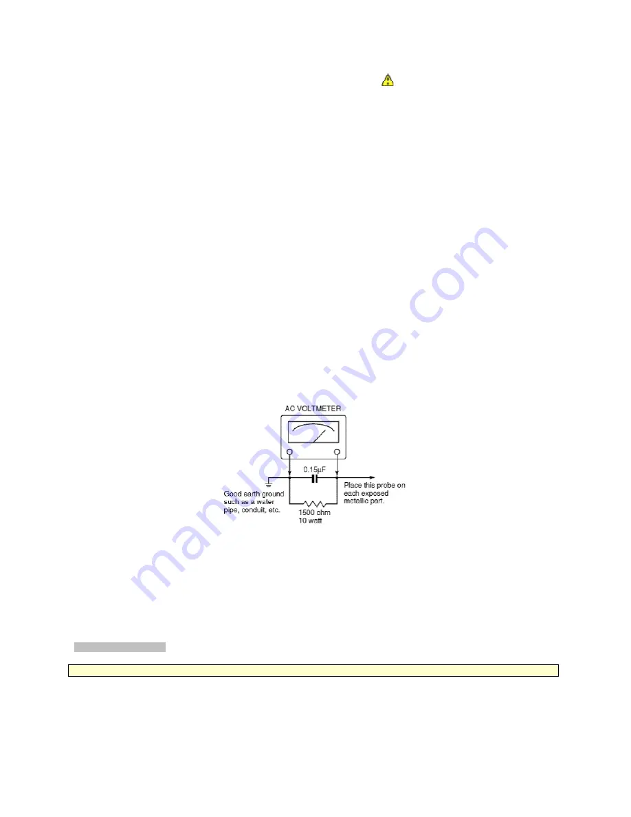
Connect a 1500 ohm 10 watt resistor, paralleled by a 0.15 µF, AC type capacitor, between a known good earth ground (water pipe,
conduit, etc.) and the exposed metallic parts, one at a time. Measure the AC voltage across the combination of 1500 ohm resistor
and 0.15 µF capacitor. Reverse the AC plug at the AC outlet and repeat AC voltage measurements for each exposed metallic part.
Voltage measured must not exceed 0.3 volts rms. This corresponds to 0.2 milliamps AC. Any value exceeding this limit constitutes a
potential shock hazard and must be corrected immediately.
Product Safety Notice
Many electrical and mechanical parts in this chassis have special safety-related characteristics. These characteristics are often
overlooked in a visual inspection. The protection afforded by them cannot necessarily be obtained by using replacement
components rated for higher voltage, wattage, etc. Replacement parts which have these special safety characteristics are identified
in this manual and its supplements. Electrical components having such features are identified by the international hazard symbols
on the schematic diagram and the parts list. Before replacing any of these components, read the parts list in this manual carefully.
The use of substitute replacement parts which do not have the same safety as specified in the parts list may create electrical shock,
fire, or other hazards.
SAFETY INSTRUCTION
WARNING:
The metal edges of the LCD module are sharp,
handle it with care.
The LCD module can easily be damaged during disassembly or reassembly; therefore, always observe the following precautions
when handling the module.
1.
In the event that the screen is damaged or the liquid crystal (fluid) leaks, do not breathe in, drink, or touch this fluid. Such
actions could cause toxicity or skin irritation. If this fluid should enter the mouth, rinse the mouth thoroughly with water. If the
2
2
Summary of Contents for 42HL67 - 42" LCD TV
Page 16: ...LOW B U02A AV TERM U03A SIGNAL U04A POWER U01A LED U03C KEY U03D Front AV U03B 15 15 ...
Page 17: ...16 16 ...
Page 18: ...17 17 ...
Page 19: ...18 18 ...
Page 20: ...19 19 ...
Page 21: ...20 20 ...
Page 22: ...Stand Exploded View A425 A426 A427 A428 A429 21 21 ...
Page 30: ...Replacement Parts List 29 ...
Page 31: ...Replacement Parts List 30 ...
Page 32: ...TOSHIBA CORPORATION 1 1 SHIBAURA 1 CHOME MINATO KU TOKYO 105 8001 JAPAN ...


