- 5 -
6. SELF DIAGNOSTIC FUNCTION
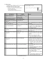
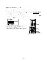
1) Press “9” button on Remote Control during display of adjustment menu in the service mode.
The diagnosis will begin to check if interface among IC’s is executed properly.
2) During diagnosis, the following displays are shown.
Part number of microprocessor (IC609)
Operation number of protection circuit (The number of times of the power supply OFF by fan stop) . . . . “000” is normal.
BUS line check
“OK” ................... Normal
“SCL-GND” or “NG” ........... SCL-GND short circuit
“SDA-GND” or “NG” ........... SDA-GND short circuit
“SCL-SDA” or “NG” ............ SCL-SDA short circuit
BUS line ACK (acknowledge) check
“OK” ................... Normal
Sync. signal check
Green display ..... Normal
Red display ........ NG
MAIN ........ Main sync
SUB .......... Sub sync (when turn on the PIP)
ID code for TV Set
Version of "EEP"
Data for "OPT"
SELF CHECK
NO. 23 * * * * * *
POWER : 000
BUS LINE : OK
BUS CONT : OK
BLOCK : MAIN SUB
SET ID : 80
E2P VER : 08
OPT1 : 00 OPT2 : A0
SW VER : DLE May 13 2004 17:**:**
HDMI
NO ********
ERR CDDE : 00
BEP
SW VER : 42
E2R VER : 02
TIME
TV
: ******
LAMP : ****
Thermo1 : +51
Thermo2 : +50
Temperature of DMD
Temperature of the color wheel neighborhood
Software version history
HDMI Software
NO *****
.....Serial No.
ERR CODE .....Error Code
BEP Software Version
SW VER : **..... Version
E2P VER : **
EEP ROM Version
Use time
TV
.....TV set on time (hour)
LAMP .....LAMP set on time (hour)
(It may shift from TV set on time.)


