– 16 –
GENERAL ADJUSTMENTS
SPECIFIC INFORMATIONS
NOTES
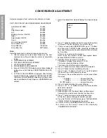
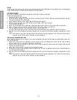
In many cases, color misconvergence may be corrected by returning HIT and WID data in main deflection side to initial adjusting
values. Following cases will surely require readjustment of convergence.
CRT REPLACEMENT
When CRT is replaced, main deflection readjustment and color matching are required.
Perform following procedures.
1. Replace two CRT’s of blue and red.
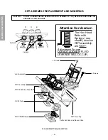
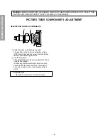
2. Perform horizontal adjustment for blue and red yokes on base of green CRT data. Mount yoke and velocity mod. coil align-
ment, pushing towards CRT without gap.
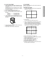
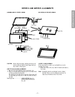
3. Adjust alignment of blue and red. (Refer Alignment adjustment for details.)
4. Rotating centering magnet, adjust CRT centers of red and blue to CRT center of green.
(Picture position adjustment)
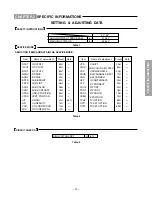
5. Adjust HIT and WID data of main deflection, and decide data at the most precise screen comparing to green data.
6. Adjust convergence of screen picture for color matching. Do not move green one at this time.
7. After convergence adjustment of screen picture finishes, replace green CRT.
For green CRT as well, repeat steps 2 to 5 above on bases of red and blue color matching to adjust convergence.
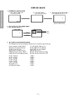
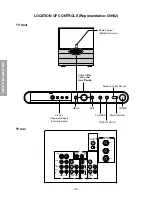
8. Execute TOUCH FOCUS following instructions displayed on the screen after finishing convergence adjustments of all the
colors.
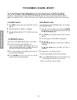
Note: Press button "7" again after "PLEASE PUSH TOUCH FOCUS" has been displayed. Then, TOUCH FOCUS will not be
executed, and the current state of convergence will be displayed.
REPLACING CONVERGENCE UNIT
When replacing convergence unit, picture screen require readjustment basically, but the following method allows process be
reduced considerably.
1. Replace the memory (Q713) on defective unit with memory on new unit. Mounting the unit on the SET after the above
working realizes picture screen before replacement immediately.
2. Mount unit which has old memories, on SET and turn it on. Screen shows whole picture looks like straightly shifted towards
vertical or horizontal direction.
3. Adjust again centers of green, red and blue with centering magnets.
4. Check picture screen for slight disparity of color and picture size. If necessary, add some adjustments of main deflection and
color matching of convergence.
5. Execute TOUCH FOCUS following instructions displayed on the screen after finishing convergence adjustments of all the
colors.
Note: Press button "7" again after "PLEASE PUSH TOUCH FOCUS" has been displayed. Then, TOUCH FOCUS will not be
executed, and the current state of convergence will be displayed.
Summary of Contents for 50H82
Page 24: ... 25 26 THIS PAGE IS INTENTIONALLY LEFT BLANK ...
Page 45: ... 47 48 SIGNAL BOARD PD0639A BOTTOM FOIL SIDE ...
Page 46: ...DEF POWER BOARD PD0640A BOTTOM FOIL SIDE 49 50 ...
Page 47: ... 51 A V BOARD PD0075C BOTTOM FOIL SIDE ...
Page 48: ... 52 SRS 3D BOARD PD0644A BOTTOM FOIL SIDE ...
Page 50: ... 54 DIGI CONV BOARD PD0638C BOTTOM FOIL SIDE ...
Page 57: ...CIRCUIT BLOCK DIAGRAM 61 62 ...

