background image

– 7 –

GENERAL ADJUSTMENTS

SPECIFIC INFORMATIONS

R, G, B FOCUS ADJUSTMENT

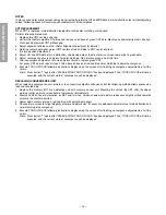
1. Before adjusting the R, G, B FOCUS, remove the 4 screws

of Lens Assembly which is fixed on the CRT Assembly.
(See page 4.)
Then turn around the Lens Assembly by 180˚ to adjust
the fastening screw (Fig. a) and fasten the 4 screws to
secure Lens Assembly.

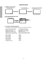
2. Select the adjustment mode. (See page 10.)
3. Press “7” button to display the built-in cross-hatch.
4. Press “0” and “RTN” buttons to make the picture a single

Red color.

100 button ................ to erase Red color
0 button .................... to erase Green color
RTN button .............. to erase Blue color.

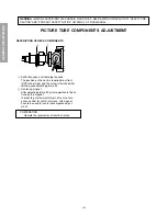
5. Loosen the fasten screw and adjust Red lens focus to best

focusing point of picture center. Then fasten the screw.
(See Fig. a.)

Fig. a

6. Adjust FOCUS VR “R” of FOCUS PACK to find best fo-

cusing point of picture center.

7. Repeat steps 3 to 5 for Green and Blue colors.

TILT ADJUSTMENT

Rotate R, G, B deflection yoke so that picture becomes hori-
zon, then fasten screw.

CENTERING ADJUSTMENT

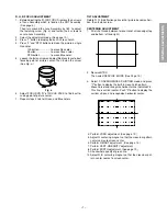
1. Stretch a thread between two center of screen edge (top

and bottom, left and right).

2. Receive NTSC.

Then select SERVICE  MODE. (See Page 10.)

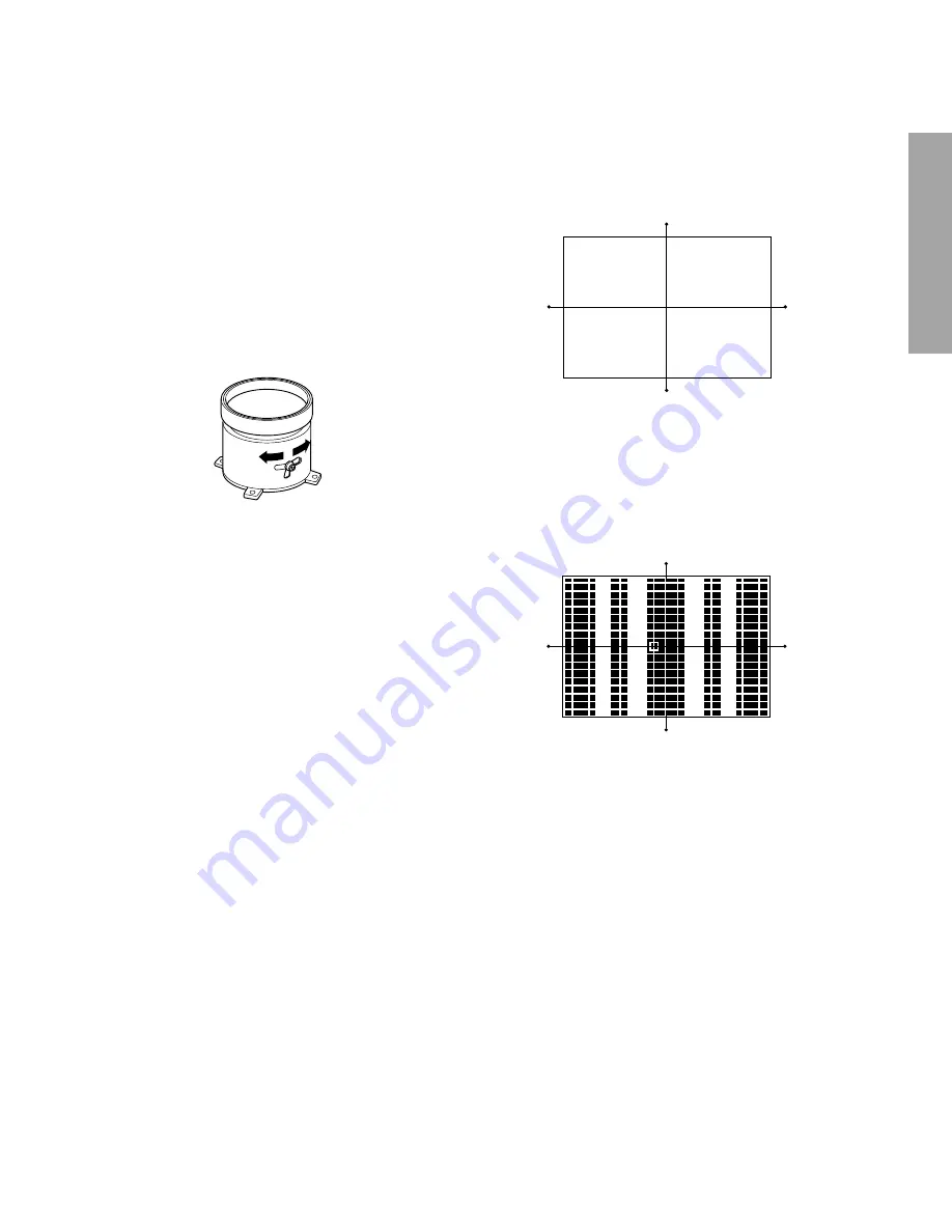
3. Select  CONVERGENCE ADJUSTING mode, and press

"7" button to display the built-in cross-hatch pattern.
Move Cursol and recognize horizontal line indicated Y:4.
This line is vertical center. Push "9" button to display the
vertical stripes, and recognaize horizontal center.

4. Perform VCEN adjustment. (See page 12.)
5. Adjust G centering magnet so that the cross-bar pattern

center comes to screen center.

6. Perform HEIGHT adjustment . (See page 13.)
7. Perform VERT. LINEARITY adjustment.
8. Perform WIDTH adjustment. (See page 12.)
9. Check whole quality of green line.

10. Adjust R, B centering magnet so that the cross-bar pat-

tern center comes to screen center.

Summary of Contents for 50H82

Page 1: ...TOSHIBA CORPORATION 1 1 SHIBAURA 1 CHOME MINATO KU TOKYO 105 8001 JAPAN FILE NO 020 200207 SERVICE MANUAL PUBLISHED IN JAPAN Jun 2002 So COLOR TELEVISION N2PSP Chassis 50H82 65H82 TAC0264 TAC0263 ...

Page 2: ...9 SERVICE MODE 10 ELECTRICAL ADJUSTMENT 12 CONVERGENCE ADJUSTMENT 14 SCREEN AND MIRROR ALIGNMENTS 17 CIRCUIT CHECKS 18 CHAPTER 2 SPECIFIC INFORMATIONS SETTING ADJUSTING DATA 19 LOCATION OF CONTROLS 20 PROGRAMMING CHANNEL MEMORY 22 MECHANICAL DISASSEMBLY 23 CHASSIS REPLACEMENT PARTS LIST 27 PC BOARDS BOTTOM VIEW 47 TERMINAL VIEW OF TRANSISTORS 59 CIRCUIT BLOCK DIAGRAM 61 SPECIFICATIONS END APPENDIX...

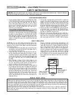
Page 3: ...ture tube away from the unprotected body while handling 3 When replacing a chassis in the cabinet always be cer tain that all the protective devices are put back in place such as non metallic control knobs insulating covers shields isolation resistor capacitor network etc 4 Before returning the set to the customer always perform an AC leakage current check on the exposed metallic parts of the cabi...

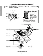
Page 4: ... Mounting 4 Screws CRT ASSEMBLY REPLACEMENT AND MOUNTING CAUTION DO NOT LOOSEN THE HEX HEAD BOLTS WITH SPRINGS 12 PCS BECAUSE THOSE ARE FOR SEALING OF CRT COOLANT Lens and Neck Components View Attention Serviceman The Hex Head Bolts with Springs see sketch used on CRT assembly are NOT Adjustment Screws DO NOT LOOSEN FLUID LEAKAGE WILL OCCUR 8 o clock 4 o clock R G B ...

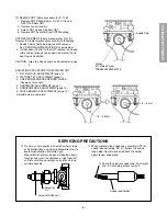
Page 5: ...ILT ADJUSTMENT page 7 3 USER CONVERGENCE CENTER CHECK See owner s manual 4 CENTERING ADJUSTMENT page 7 5 CONVERGENCE ADJUSTMENT page 14 6 WHITE BALANCE ADJUSTMENT page 13 Adjustments are complete SERVICING PRECAUTIONS Check the point of anode lead in a straight line if it is winding please revise it Anode lead holder Do not use a magnetized screw driver for screws of Deflection Yoke and Velocity M...

Page 6: ...ection yoke and convergence yoke The position on the neck is required most front CRT funnel side and the screw is fastened after rotating yoke adjusting picture tilt Centering magnet After adjusting picture tilt picture position is finally fixed by this magnet In order to get maximum margin of user conver gence control for center of screen this magnet have to be used for center convergence adjust ...

Page 7: ...int of picture center 7 Repeat steps 3 to 5 for Green and Blue colors TILT ADJUSTMENT Rotate R G B deflection yoke so that picture becomes hori zon then fasten screw CENTERING ADJUSTMENT 1 Stretch a thread between two center of screen edge top and bottom left and right 2 Receive NTSC Then select SERVICE MODE See Page 10 3 Select CONVERGENCE ADJUSTING mode and press 7 button to display the built in...

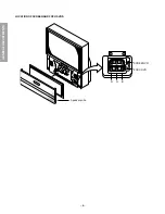
Page 8: ... 8 GENERAL ADJUSTMENTS SPECIFIC INFORMATIONS LOCATION OF SCREEN AND FOCUS VR S SCREEN VR FOCUS VR R G B Speaker grille ...

Page 9: ... TPA5007 Fig a 1 When replacing Anode Lead or Anode Cap with new one remove Lead Holder from old lead as shown in figure below and put it on new lead Do not throw away Lead Holder NOTE THE LEAD HOLDER IS ATTACHEDTOTPA5007 Z450 BUT IS NOT ATTACHED TO ANODE LEAD AND ANODE CAP RUBBER BOOT IS AT TACHED TO ANODE LEAD AND ANODE CAP 2 Detaching Lead Holder Fig b RUBBER BOOT OLD ANODE LEAD or ANODE CAP LO...

Page 10: ...key entry during display of adjustment menu provides special functions Screen adjustment mode ON OFF TV ANT VIDEO button on TV Selection of the adjustment items Channel s t on TV or Remote Change of the data value Volume s t on TV or Remote Adjustment menu mode ON OFF MENU button on TV Initialization of the memory QA02 RECALL Channel button on TV s Initialization of the self diagnostic data RECALL...

Page 11: ... the PIP ID code for TV Set Version of EEP Data for OPT 4 SELECTING THE ADJUSTING ITEMS 1 Every pressing of CHANNEL s button in the service mode changes the adjustment items in the order of table 2 t button for reverse order Refer to table 2 for preset data of adjustment mode See SETTING ADJUSTING DATA on page 19 5 ADJUSTING THE DATA 1 Pressing of VOLUME s or t button will change the value of data...

Page 12: ...teps NOTE Check the horizontal picture position is correct 0 Blue Magenta 2 3 1 8V0 P 1 Receive color bar signal from color bar generator 2 Adjust the BRIGHTNESS and CONTRAST to the center RESET status 3 Connect oscilloscope to TP501on the MAIN board 4 Enter the service mode then select SCOL 5 Adjust the data value to achieve 1 8V0 p of blue bar on scope 6 Check the picture with off air signal ELE...

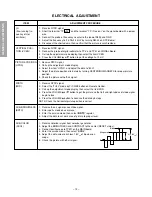
Page 13: ... RCUT GCUT BCUT RDRV BDRV 1 Press RESET button on TV or remote hand set 2 Call up the adjustment mode display then adjust the data of items RCUT GCUT and BCUT to 80 3 Press TV ANT VIDEO button on TV 4 Gradually rotate R G and B SCREEN volume of FOCUS PAC page 9 clock wise or counterclockwise until the raster appears slightly on the CRT through the each lens and leave them Look into the lens in ord...

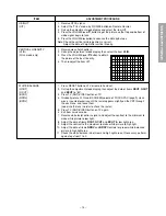
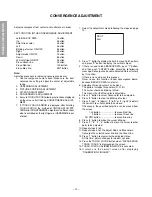
Page 14: ...ton and then push ENTER button according to following message Convergence become adjusted state at factory by this action If there is no need pass this process Never to use this function to new convergence board because BACKUP DATA is not exist 4 Adjustment around cursor can be done The pattern includes three colors R G B The cursor should be blinking in Red This means that the Red color is adjust...

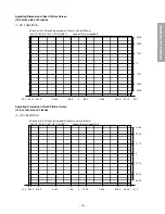
Page 15: ...1 226 2 301 6 50 inches 16 9 Screen Size horizontal 1106mm Vertical 622mm QH173 16KB CHIP1 UFO BANK1 Vspan37 7mm Hspan88 5 Adjusting Dimension of Each Picture Screen 16 9 screen size 65 inches 1 HD 1080I NTSC 31 0 690 0 575 0 345 0 0 115 0 115 0 345 0 575 0 690 0 65 inches 16 9 Screen Size horizontal 1442mm Vertical 810mm QH173 16KB CHIP1 UFO BANK1 Vspan49 1mm Hspan115 0 31 0 392 3 294 3 147 3 0 1...

Page 16: ...djust convergence 8 Execute TOUCH FOCUS following instructions displayed on the screen after finishing convergence adjustments of all the colors Note Press button 7 again after PLEASE PUSH TOUCH FOCUS has been displayed Then TOUCH FOCUS will not be executed and the current state of convergence will be displayed REPLACING CONVERGENCE UNIT When replacing convergence unit picture screen require readj...

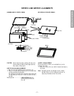
Page 17: ...ified cloth into which a cleaning liquid has been soaked Cleaning liquid LENS LUSTER Manufac tured by Edmund Scientific Co etc HOW TO CLEAN SCREEN When cleaning the screen use a soft cloth so as not to damage the screen 1 Wipe the screen with a dry cloth to remove moisture on the screen Note Absolutely do not use detergent water alcohol benzine thinner etc for cleaning in order not to wipe away th...

Page 18: ...he FS circuit more than 5 seconds to reset Then turn the receiver on to produce a normal picture Location No Name 50 65 T461 C407 C408 C441 C432 C433 TFB3092AD 4700pF 3 8200pF 5 4700pF 3 8200pF 5 1200pF 3 ANODE VOLTAGE MEASURING METHOD CAUTION Take extra precaution when measuring this high voltage High voltages are also present in surrounding circuit boards CRT DRIVE assem bly DEFLECTION assembly ...

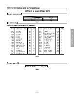
Page 19: ... POSITION HEIGHT V LINEARITY V S CORRECTION PICTURE WIDTH RCUT GCUT BCUT RDRV BDRV BRTC TNTC SCOL SCNT HPOS VPOS HIT LIN VSC WID Preset Data 80H 80H 80H 40H 40H 80H 48H 0BH 15H 80H 01H 31H 14H 10H 1FH 55H Table 2 CIRCUIT CHECKS Table 3 Item Name of adjustment Preset Data VPS COLC VCP PARA CNR HCP VFC PHUE PCNT PCOL VCEN TVOP OPT1 OPT2 V SHIFT SUB COLOR CEN NTSC V COMPENSATE E W PARABOLA DPC E W CO...

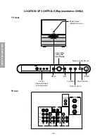
Page 20: ...2 VIDEO L MONO R AUDIO MONO L AUDIO R L R AUDIO P Y P B R L VAR AUDIO ANT 75Ω VIDEO 2 VIDEO 1 OUT IN IN COLOR STREAM HD 1 L R AUDIO P Y P B R IN COLOR STREAM HD 2 MENU CHs CHt Channel ts Volume T S Menu tsT S TV VIDEO TOUCH FOCUS POWER Power indicator Automatic Light Sensor EXIT Video 3 Video audio inputs behind the door Remort sensor Behibd the screen POWER VOL T SVOL ...

Page 21: ...TILL SWAP TV VCR REW FF STOP SOURCE FAV FAV F A V O R I T E E X I T P I C S I Z E C C A P T 1 4 7 2 5 8 3 6 9 0 100 MENU ENTER LIGHT TV CABLE VCR switch Set to TV to control the TV MUTE Channel Number FAVORITE ENTER FAV t C CAPT POP CH t RECALL POWER TIMER TV VIDEO CHANNEL s t VOLUME s t CH RTN POP CH s FAV s EXIT PIC SIZE POP functions For TV and CABLE modes s t T S ...

Page 22: ...will automatically cycle through all the TV or CABLE channels selected by the TV CABLE function and store active channels in the channel memory 3 When channel programming is complete you will see the message to the right appears 4 Press CHANNEL s or t to make sure the channel programming has been done properly ADD ERASE function After performing the CH PROGRAM function you can add or erase specifi...

Page 23: ...val 3 Front Mask Removal 4 Shield Plate Lens Removal 5 Mirror Removal 6 Back Board Removal 7 Light Box Removal K111 K112 K113 4 screws K601 5 screws 3 screws A160 A421 A424 5 screws A102 A101 A001 A201 A268 2 screws A202 A214 A213 A224 K501 K502 K503 8 screws 5 screws 6 screws ...

Page 24: ... 25 26 THIS PAGE IS INTENTIONALLY LEFT BLANK ...

Page 25: ... C346 24669100 ELECTROLYTIC 50V 10UF M 3A C347 24085946 ELECTROLYTIC NONPOLAR 16V 10UF M 3A C348 24503045 PLASTIC FILM 63V 0 22UF J C349 24503045 PLASTIC FILM 63V 0 22UF J C351 24503041 PLASTIC FILM 63V 0 1UF J C352 24669229 ELECTROLYTIC 50V 2 2UF M 3A C353 24669010 ELECTROLYTIC 50V 1 0UF M 3A C354 24567823 PLASTIC FILM 50V 82000PF J C355 24567563 PLASTIC FILM 50V 56000PF J C356 24665220 ELECTROLY...

Page 26: ...LECTROLYTIC 50V 1 0UF M 3A C531 24666101 ELECTROLYTIC 16V 100UF M 3A C532 24666100 ELECTROLYTIC 10V 10UF M 3A C536 24109103 CERAMIC CHIP 50V B 0 01UF K C537 24109103 CERAMIC CHIP 50V B 0 01UF K C547 24109103 CERAMIC CHIP 50V B 0 01UF K C551 24100104 CERAMIC CHIP 25V F 0 1UF Z C552 24100104 CERAMIC CHIP 25V F 0 1UF Z C553 24100104 CERAMIC CHIP 25V F 0 1UF Z C554 24100104 CERAMIC CHIP 25V F 0 1UF Z ...

Page 27: ...10000PF Z C904 24436561 CERAMIC DISC 50V SL 560PF J C907 24214101 CERAMIC DISC 500V B 100PF K C908 24436390 CERAMIC DISC 50V SL 39PFJ C909 24794221 ELECTROIYTIC 16V 220UF M C911 24211102 CERAMIC DISC 2KV B 1000PF K C912 24794101 ELECTROLYTIC 16V 100UF M C913 24232103 CERAMIC DISC 50V F 10000PF Z C914 24436681 CERAMIC DISC 50V SL 680PF J C915 24679330 ELECTROLYTIC 250V 33UF M 3A C916 24794102 ELECT...

Page 28: ...K CA701 24092538 CERAMIC CHIP 10V F 1UF Z CA705 24666100 ELECTROLYTIC 10V 10UF M 3A CB01 24794470 ELECTORLYTIC 16V 47UF M CB05 24666100 ELECTROLYTIC 10V 10UF M 3A CB13 24085970 ELECTROLYTIC NONPOLAR 16V 10UF M 7L CB14 24105331 CERAMIC CHIP 50V CH 330PF J CB15 24794100 ELECTROLYTIC 16V 10UF M CB62 24105331 CERAMIC CHIP 50V CH 330PF J CB90 24109103 CERAMIC CHIP 50V B 0 01UF K CB91 24666100 ELECTROLY...

Page 29: ...100104 CERAMIC CHIP 25V F 0 1UF Z CH521 24105100 CERAMIC CHIP 50V CH 10PF D CH522 24590222 PLASTIC FILM 50V 2200PF J CH523 24100103 CERAMIC CHIP 50V F 0 01UF Z CH524 24105821 CERAMIC CHIP 25V CH 820PF J CH526 24105050 CERAMIC CHIP 50V CH 5PF C CH527 24105181 CERAMIC CHIP 50V CH 180PF J CH541 24105100 CERAMIC CHIP 50V CH 10PF D CH542 24590222 PLASTIC FILM 50V 2200PF J CH543 24100103 CERAMIC CHIP 50...

Page 30: ...366101 CARBON FILM 1 6W 100 OHM J R151 24366562 CARBON FILM 1 6W 5 6K OHM J R152 24366103 CARBON FILM 1 6W 10K OHM J R171 24011103 CHIP METAL FILM 1 20W 10K OHM J R172 24011273 CHIP METAL FILM 1 20W 27K OHM J R173 24011103 CHIP METAL FILM 1 20W 10K OHM J R174 24011273 CHIP METAL FILM 1 20W 27K OHM J R205 24011101 CHIP METAL FILM 1 20W 100 OHM J R206 24011102 CHIP METAL FILM 1 20W 1K OHM J R241 243...

Page 31: ...439 24366103 CARBON FILM 1 6W 10K OHM J R440 24366103 CARBON FILM 1 6W 10K OHM J R441 24366474 CARBON FILM 1 6W 470K OHM J R442 24366103 CARBON FILM 1 6W 10K OHM J R443 24366562 CARBON FILM 1 6W 5 6K OHM J R444 24366562 CARBON FILM 1 6W 5 6K OHM J R445 24366472 CARBON FILM 1 6W 4 7K OHM J R446 24366103 CARBON FILM 1 6W 10K OHM J R447 24366152 CARBON FILM 1 6W 1 5K OHM J R448 24366333 CARBON FILM 1...

Page 32: ... CARBON FILM 1 6W 27K OHM J R762 24366563 CARBON FILM 1 6W 56K OHM J R763 24552331 OXIDE METAL FILM 1 2W 330 OHM J R764 24366470 CARBON FILM 1 6W 47 OHM J R765 24552100 OXIDE METAL FILM 1 2W 10 OHM J R766 24366470 CARBON FILM 1 6W 47 OHM J R767 24552221 OXIDE METAL FILM 1 2W 220 OHM J R768 24366751 CARBON FILM 1 6W 750 OHM J R769 24366122 CARBON FILM 1 6W 1 2K OHM J R770 24553330 OXIDE METAL FILM ...

Page 33: ...1 6W 5 6K OHM J R992 24366153 CARBON FILM 1 6W 15K OHM J R995 24366330 CARBON FILM 1 6W 33 OHM J R4005 24366102 CARBON FILM 1 6W 1K OHM J R4010 24366102 CARBON FILM 1 6W 1K OHM J R4011 24366223 CARBON FILM 1 6W 22K OHM J R4012 24366223 CARBON FILM 1 6W 22K OHM J R4013 24366103 CARBON FILM 1 6W 10K OHM J R4014 24366222 CARBON FILM 1 6W 2 2K OHM J R4015 24000633 METAL FILM 1 4W 10K OHM F R4016 24366...

Page 34: ...23 CHIP METAL FILM 1 20W 12K OHM J R7890 24011471 CHIP METAL FILM 1 20W 470 OHM J R7891 24011471 CHIP METAL FILM 1 20W 470 OHM J R7893 24011101 CHIP METAL FILM 1 20W 100 OHM J R7894 24011472 CHIP METAL FILM 1 20W 4 7K OHM J R7895 24011103 CHIP METAL FILM 1 20W 10K OHM J R7896 24011221 CHIP METAL FILM 1 20W 220 OHM J R7897 24011103 CHIP METAL FILM 1 20W 10K OHM J R7898 24011472 CHIP METAL FILM 1 20...

Page 35: ...L FILM 1 2OW 15K OHM J RB15 24366471 CARBON FILM 1 6W 470 OHM J RB15 24011153 CHIP METAL FILM 1 2OW 15K OHM J RB16 24011471 CHIP METAL FILM 1 20W 470 OHM J RB17 24011332 CHIP METAL FILM 1 20W 3 3K OHM J RB19 24366470 CARBON FILM 1 6W 47 OHM J RB41 24366151 CARBON FILM 1 6W 150 OHM J RB61 24011222 CHIP METAL FILM 1 20W 2 2K OHM J RB62 24011103 CHIP METAL FILM 1 20W 10K OHM J RB64 24011332 CHIP META...

Page 36: ...ILM 1 20W 220K OHM J RH337 24011224 CHIP METAL FILM 1 20W 220K OHM J RH338 24011224 CHIP METAL FILM 1 20W 220K OHM J RH339 24011101 CHIP METAL FILM 1 20W 100 OHM J RH340 24011101 CHIP METAL FILM 1 20W 100 OHM J RH341 24011101 CHIP METAL FILM 1 20W 100 OHM J RH342 24011101 CHIP METAL FILM 1 20W 100 OHM J RH343 24011102 CHIP METAL FILM 1 20W 1K OHM J RH344 24011102 CHIP METAL FILM 1 20W 1K OHM J RH3...

Page 37: ... 6W 100 OHM J RS48 24366101 CARBON FILM 1 6W 100 OHM J RS49 24366103 CARBON FILM 1 6W 10K OHM J RS51 24366103 CARBON FILM 1 6W 10K OHM J RS52 24366103 CARBON FILM 1 6W 10K OHM J RS53 24366103 CARBON FILM 1 6W 10K OHM J RS54 24366103 CARBON FILM 1 6W 10K OHM J RS120 24552821 OXIDE METAL FILM 1 2W 820 OHM J RS121 24011103 CHIP METAL FILM 1 20W 10K OHM J RS122 24011103 CHIP METAL FILM 1 20W 10K OHM J...

Page 38: ...KE TDY707PDE L472 23102457 VM COIL 29 1VM4T3PLEAD MAG 1102 L473 23102457 VM COIL 29 1VM4T3PLEAD MAG 1102 L474 23102457 VM COIL 29 1VM4T3PLEAD MAG 1102 L502 23289120 COIL PEAKING TRF4120AF L503 23289120 COIL PEAKING TRF4120AF L510 23103845 COIL COMMONMODE TEM2030AY L511 23103845 COIL COMMONMODE TEM2030AY L701 23237987 COIL PEAKING TRF4100AC L702 23261974 COIL FERRITE BEAD HC5 035 L704 23103859 COIL...

Page 39: ...0119059 IC OP AMP TA75902P J Q322 23905266 IC TA8859CP Q323 23314965 TRANSISTOR KTC3198 Y Q324 70119059 IC OP AMP TA75902P J Q325 23314965 TRANSISTOR KTC3198 Y Q326 23314962 TRANSISTOR KTA1266 Y Q327 23314965 TRANSISTOR KTC3198 Y Q328 23114462 TRANSISTOR RN1202 Q329 23114461 TRANSISTOR RN1203 Q400 23205079 TRANSISTOR 2SC4686A Q401 23205166 TRANSISTOR FET 2SK2962 Q402 23314962 TRANSISTOR KTA1266 Y ...

Page 40: ...TOR 2SA1015 Y TE Q972 23114425 TRANSISTOR 2SA1015 Y TE Q973 23114735 TRANSISTOR 2SA102 Y C Q974 23114433 TRANSISTOR 2SC1815 Y Q975 23114437 TRANSISTOR 2SC752GTM Y QA01 23009229 IC MCU 1CHIP 16BIT 4M 64 QA02 23906642 IC AT24C64 10PC QA70 23319935 IC MM1096BS QA71 23205057 TRANSISTOR KTC3875Y QA72 23205057 TRANSISTOR KTC3875Y QA80 23906295 IC UPC29M33HB QA81 70200563 IC RESET VS 2 9V PST9129 QB01 23...

Page 41: ...ER MTZJ2 0B D521 23118041 DIODE MA111 D522 23118041 DIODE MA111 D523 23118041 DIODE MA111 D530 23316586 DIODE ZENER MA8082 H D531 23316584 DIODE ZENER CHIP VZ7 77 8 17V MA8082 L D532 23118822 DIODE ERB12 02 D533 23316586 DIODE ZENER MA8082 H D534 23316792 DIODE SC215 D535 23316591 DIODE ZENER MA8100 M D601 23118041 DIODE MA111 D602 23118041 DIODE MA111 D603 23118041 DIODE MA111 D604 23118041 DIODE...

Page 42: ...16672 DIODE ZENER MTZJ5 6B DH301 23316672 DIODE ZENER MTZJ5 6B DH301 23316672 DIODE ZENER MTZJ5 6B DH302 23316672 DIODE ZENER MTZJ5 6B DH303 23316672 DIODE ZENER MTZJ5 6B DH304 23316672 DIODE ZENER MTZJ5 6B DH305 23316672 DIODE ZENER MTZJ5 6B DH306 23316672 DIODE ZENER MTZJ5 6B DH307 23316672 DIODE ZENER MTZJ5 6B DH308 23316672 DIODE ZENER MTZJ5 6B DH309 23118859 DIODE 1SS133 DH310 23118859 DIODE ...

Page 43: ...E GJ76 23103237 CHIP BEAD INDUCTOR 102OHM GJ77 24000445 CHIP JUMPER 1608TYPE GJ77 24000445 CHIP JUMPER 1608TYPE GJ78 24000445 CHIP JUMPER 1608TYPE GJ79 23103237 CHIP BEAD INDUCTOR 102OHM GJ80 24000445 CHIP JUMPER 1608TYPE GJ81 24000824 CHIP JUMPER 2125TYPE GJ82 24000824 CHIP JUMPER 2125TYPE GJ83 24000824 CHIP JUMPER 2125TYPE GJA33 24000445 CHIP JUMPER 1608TYPE GR99 24000445 CHIP JUMPER 1608TYPE H0...

Page 44: ...2 V903B 23086395 OTHER BLOCK COUPLING B 65H82 TUNER H001 23321411 TUNER TIM 181CH IIC PH SHINSEN EL967LW HY01 23321412 TUNER TIF 181CH IIC PH TDL EL963L ACCESSORIES K912 23306413 REMOCON HAND UNIT IR PJTVUSA CT 90086 Y101 23565646 OWNER S MANUAL ENGLISH FRENCH 50H82 65H82 CABINET PARTS A001 23411539 CABINET WOOD CABINET SHIP 50H82 A001 23411711 WOOD CAB SHIP 65H82 A102 23527171 GRILLE SPK GRILLE A...

Page 45: ... 47 48 SIGNAL BOARD PD0639A BOTTOM FOIL SIDE ...

Page 46: ...DEF POWER BOARD PD0640A BOTTOM FOIL SIDE 49 50 ...

Page 47: ... 51 A V BOARD PD0075C BOTTOM FOIL SIDE ...

Page 48: ... 52 SRS 3D BOARD PD0644A BOTTOM FOIL SIDE ...

Page 49: ... R369 R375 Q327 R376 R4036 C4 R4030 C487 R4032 C491 C354 R384 C355 C356 Q328 R378 R377 R357 C4 C4 C3 Q329 C3 R383 R382 C471 R4014 Q421 R4013 R4011 R4012 C473 R4015 R4016 C474 R4018 C476 C475 C486 R4024 R4026 R4025 C485 C484 C483 C482 C478 R4023 R4 R4 C477 C481 C439 R4020 R4033 R4021 R4034 1 7 8 14 1 1 8 9 16 E B E B E B E B E B E B E B fh ADJ 7 8 14 1 30 15 16 37 53 88 89 R4017 21 035 022 93 R4031...

Page 50: ... 54 DIGI CONV BOARD PD0638C BOTTOM FOIL SIDE ...

Page 51: ...977 R975 R978 R974 R973 R972 R971 R963 R962 R961 R964 R965 R966 R968 R967 L961 L962 C961 C962 C964 C963 R937 R936 D963 D964 D965 D966 D967 C907 R938 D904 L902 P921 Q968 R983 R984 R985 R986 R987 P915A R902 C909 C908 G994 L904 C967 R996 R995 GJ92 P908 RED DRIVE RED SCREEN E B C B E E B E B B E E B E B E E B 1 2 3 4 5 6 1 2 3 4 5 6 7 8 9 10 B G2 G1 K H H B1 V 0 P909 J901 B1 V O P900 QH301 DH301 CRT D...

Page 52: ...B B E B B E E B E 1 2 3 4 5 6 7 1 2 3 4 5 6 7 8 9 10 1 2 3 4 5 6 7 8 9 G947 L914 R9508 R9507 C9100 R918 D948 5 R900 L963 R9505 R9502 C917 D912 R9709 E R9503 P911 P909 R979 G2 G1 K H H SCREEN BLUE DRIVE BLUE B1 V 0 P916B R923 V903A C921 C925 Q922 R927 C924 D921 C922 R952 R951 Q921 D922 D P904 Q975 R929 R924 P903 D936 C926 R959 D931 D932 D933 D934 R954 R953 D929 R956 E C B B E R930 L923 E B Q971 R96...

Page 53: ... C719 C704 R715 R716 R718 C722 R724 R723 R717 C705 R725 R734 C716 R735 R739 R733 R738 R745 R737 R732 C714 R702 D721 Q720 C726 R713 Q719 R719 Q712 Q711 P708A P709A P705 D715 E C B E B C E B E E B E B E B 1 2 3 E C B 1 2 3 4 5 6 L701 P706B 1 2 3 4 1 2 3 4 5 6 G SVM G 1 2 3 P707B C712 R731 P917 R720 B E B E E B B E C C 1 2 3 B1 V 0 B E 1 2 3 4 5 6 SVM B B C780 Q783 Q782 D784 D783 R796 R794 R793 R780 ...

Page 54: ...SA08 DB01 PB11 RA76 QB01 RB04 SA06 RB01 POW MENU E B 1 2 3 4 5 6 1 2 3 4 PB13B 7 8 RB05 PB22 DB03 KB01 RB15 RB19 CB01 1 2 3 4 B1 V 0 T D V L R Y C B1 V 0 T D PV60 PV02 LV20 CV14 RV21 RV23 CV13 RV20 CV15 RV22 1 2 3 4 5 6 7 8 9 1 2 3 4 DV39 PB13A B1 V O T D FRONT BOARD PD0081 BOTTOM FOIL SIDE FRONT BOARD PD0081 BOTTOM FOIL SIDE FRONT BOARD PD0081 BOTTOM FOIL SIDE ...

Page 55: ... 2SC4544 2SA1788 2SA1306 2SA1186A 2SC752GTM 2SC2482 2SC2655 2SC4721P 2SC752 2SA562TM 2SA1015 2SC1815 2SC2878 2SC1740S 2SC2120 2SA9335 2SA1788 RN2203 RN2201 RN2004 RN1203 RN1204 RN2204 RN1205 RN1202 RN1201 2SD1554 2SD2253 2SD1556 2SD2553 2SC5143 E C B B C E BCE B CE B C E E C B E C B ON4409 B C E ...

Page 56: ...ntical with originals Before replacing any of these components read carefully the PRODUCT SAFETY NOTICE on the MANUAL for this model Do not degrade the safety of the receiver through improper servicing NOTE 1 RESISTOR Resistance is shown in ohm K 1 000 M 1 000 000 All resistors are 1 6W and 5 tolerance carbon resistor unless otherwise noted as the following marks 1 2R Metal or Metal oxide of 1 2 w...

Page 57: ...CIRCUIT BLOCK DIAGRAM 61 62 ...

Page 58: ...rst signal 75 ohm VIDEO AUDIO INPUT VIDEO 1 V p p 75 ohm negative sync AUDIO 150 mV rms 30 modulation equivalent 47 kohm ColorStreamTM Component video INPUT Y INPUT 1 V p p 75 ohm PR INPUT 0 7 V p p 75 ohm PB INPUT 0 7 V p p 75 ohm AUDIO 150mV rms 47 kohm VIDEO AUDIO OUTPUT VIDEO 1 V p p 75 ohm negative sync AUDIO 150 mV rms 30 modulation equivalent 4 7 kohm VARIABLE AUDIO OUTPUT 0 300 mV rms 30 m...

Page 59: ...TOSHIBA CORPORATION 1 1 SHIBAURA 1 CHOME MINATO KU TOKYO 105 8001 JAPAN FILE NO 020 200207 SERVICE MANUAL PUBLISHED IN JAPAN Jun 2002 So COLOR TELEVISION N2PSP Chassis 50H82 65H82 TAC0264 TAC0263 ...

Reviews: