background image

- 24 -

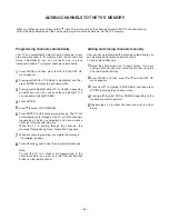
ADDING CHANNELS TO THE TV'S MEMORY

When you When you press Channel    or    , your TV will stop only on the channels stored in the TV's channel memory.
Follow the steps below and on the next page to program all active channels into the TV's memory.


Programming channels automatically

1

2

3

4

5

6

7

8

Adding and erasing channels manually

1

2

3

4

5

Your TV can automatically detect all active channels in your 
area and store them in its memory. After the channels are 
stored automatically, you can manually add or erase 
individual channels. To program channels automatically:

Press MENU, and then press   or   until the SET UP 
menu appears.

Press   or   until the TV/CABLE is highlighted, and then 
press ENTER to display the pull-down menu.

Press   or   to highlight either TV or CABLE, depending 
on which you use. If you use an antenna, highlight TV; if 
you use cable, highlight CABLE.

Press ENTER.

Press    to select CH PROGRAM.

Press ENTER to start channel programming. The TV will 
automatically cycle through all the TV or Cable channels 
(depending on which you selected), and store all active 
channels in the channel memory.
While the TV is cycling through the channels, the 
message "Programming Now-Please Wait" appears.

When channel programming is complete,the message
 "Completed" appears.

Press Channel    or    to view the programmed channels.

Note:
To tune the TV to a channel not programmed in the 
channel memory, you must use the Channel Number 
buttons on the remote control.

After you have programmed the channels automatically, you 
can manually add or erase specific channels.
To add or erase channels:

Select the channel you want to add or erase. If you are 
adding a channel, you must select the channel using the 
Channel Number buttons.

Press MENU, and then press   or   until the SET UP 
menu appears.

Press    or    to highlight ADD/ERASE, and then press 
ENTER to display the pull-down menu.

Press    or    to select ADD or ERASE, depending on the 
function you want to perform.

Repeat steps 1-4 for other channels you want to add or 
erase. 

Summary of Contents for 51HX84

Page 1: ...SERVICE MANUAL Projection Television 51HX84 57HX84 N4PS Chassis FILE NO 020 200410 ...

Page 2: ...CAL ADJUSTMENT 12 CONVERGENCE ADJUSTMENT 16 SCREEN AND MIRROR ALIGNMENTS 19 CIRCUIT CHECKS 20 CHAPTER 2 SPECIFIC INFORMATIONS SETTING ADJUSTING DATA 21 LOCATION OF CONTROLS 22 ADDING CHANNELS TO THE TV S MEMORY 24 MECHANICAL DISASSEMBLY 25 CHASSIS REPLACEMENT PARTS LIST 27 PC BOARDS BOTTOM VIEW 36 TERMINAL VIEW OF TRANSISTORS 48 CIRCUIT BLOCK DIAGRAM 51 SPECIFICATIONS END APPENDIX CIRCUIT DIAGRAM ...

Page 3: ... the unprotected body while handling 3 When replacing a chassis in the cabinet always be cer tain that all the protective devices are put back in place such as non metallic control knobs insulating covers shields isolation resistor capacitor network etc 4 Before returning the set to the customer always perform anAC leakage current check on the exposed metallic parts of the cabinet such as antennas...

Page 4: ...ASSEMBLY REPLACEMENT AND MOUNTING CAUTION DO NOT LOOSEN THE HEX HEAD BOLTS WITH SPRINGS 12 PCS BECAUSE THOSE ARE FOR SEALING OF CRT COOLANT Lens and Neck Components View Attention Serviceman The Hex Head Bolts with Springs see sketch used on CRT assembly are NOT Adjustment Screws DO NOT LOOSEN FLUID LEAKAGE WILL OCCUR R G B ...

Page 5: ... 3 USER CONVERGENCE CENTER CHECK See owner s manual 4 CENTERING ADJUSTMENT page 7 5 CONVERGENCE ADJUSTMENT page 16 6 WHITE BALANCE ADJUSTMENT page 12 Adjustments are complete SERVICING PRECAUTIONS Check the point of anode lead in a straight line if it is winding please revise it Anode lead holder Do not use a magnetized screw driver for screws of Deflection Yoke and Velocity Modulation Coil to avo...

Page 6: ...rgence yoke The position on the neck is required most front CRT funnel side and the screw is fastened after rotating yoke adjusting picture tilt Centering magnet After adjusting picture tilt picture position is finally fixed by this magnet In order to get maximum margin of user conver gence control for center of screen this magnet have to be used for center convergence adjust ment PREPARATION Oper...

Page 7: ...ure center 7 Repeat steps 3 to 5 for Green and Blue colors TILT ADJUSTMENT Rotate R G B deflection yoke so that picture becomes hori zon then fasten screw CENTERING ADJUSTMENT 1 Stretch a thread between two center of screen edge top and bottom left and right 2 Receive NTSC Then select SERVICE MODE See Page 10 3 Select CONVERGENCE ADJUSTING mode and press 7 button to display the internal net patter...

Page 8: ... 8 LOCATION OF SCREEN AND FOCUS VR S FOCUS COVER Speaker grille G B R SCREEN ...

Page 9: ...with new one remove Lead Holder from old lead as shown in figure below and put it on new lead Do not throw away Lead Holder NOTE THE LEAD HOLDER ISATTACHED TO TPA5011 Z450 BUT IS NOT ATTACHED TO ANODE LEAD ANDANODE CAP RUBBER BOOT ISAT TACHED TO ANODE LEAD AND ANODE CAP 2 Detaching Lead Holder Fig b RUBBER BOOT OLD ANODE LEAD or ANODE CAP LOCK LEAD HOLDER Cut here rubber boot and lead together to ...

Page 10: ... entry during display of adjustment menu provides special functions Screen adjustment mode ON OFF TV ANT VIDEO button on TV Selection of the adjustment items Channel on TV or Remote Change of the data value Volume on TV or Remote Adjustment menu mode ON OFF MENU button on TV Initialization of the memory QA02 RECALL Channel button on TV Initialization of the self diagnostic data RECALL Channel butt...

Page 11: ...r OPT Part number of HDMI microprocessor HDMI error code 4 SELECTING THE ADJUSTING ITEMS 1 Every pressing of CHANNEL button in the service mode changes the adjustment items in the order of table 2 button for reverse order Refer to table 2 for preset data of adjustment mode See SETTING ADJUSTING DATA on page 21 5 ADJUSTING THE DATA 1 Pressing of VOLUME or button will change the value of data in the...

Page 12: ...2 Using the data up and down keys cycle through the adjustments for RED DRIVE BLUE DRIVE RED BIAS and BLUE BIAS Adjust RED DRIVE BLUE DRIVE for bright area and adjust RED BIAS and BLUE BIAS for dark area 3 Continue to make adjustments color temperature to spec on each area 1 Receive channel 3 Sub Bright pattern 2 Go into BRTC of service mode 3 Press DATA UP DOWN to adjust Sub Bright level to spec ...

Page 13: ...t 1 Receive green single color by shielding jig 2 Receive the Dot Cross pattern 3 Adjust Green electrical focus Adjust Green electrical focus VR on focus pack Z410 for best center focus If the focus blur on screen center and circumference adjust the electrical focus is best point on all of screen 4 Adjust Green lens focus Receive the Dot Cross pattern Adjust Green lens for best center focus Green ...

Page 14: ...lor by shielding jig 2 Receive the Dot Cross pattern 3 Adjust Blue electrical focus Adjust Blue electrical focus VR on focus pack Z410 for best center focus The Brightness is minimum point of Blue 4 Adjust Blue lens focus Receive the Dot Cross pattern Adjust the Blue lens for best center focus After easy lens adjustment turn to right side lens focus screw and so dot cross has flare Next turn left ...

Page 15: ... Repeat 3 6 if necessary readjust 2 pole magnets PROCESS Adjust single color by shielding jig 1 Receive the Dot Pattern of signal generator white dot black back 2 Rotate Green focus VR for a high focus clockwise 3 Adjust the 4 pole magnet if necessary to ensure dots are circles not elliptical 4 Adjust Green electrical focus on Dot Cross pattern 5 Receive the RETOMA pattern and check the centering ...

Page 16: ...FOCUS ERROR is displayed 1 Check the connection between four sensors and Convergence Unit 2 Check the geometry of internal net pattern See Page 14 If any problem cannnot be found hardware might have problem 1 Receive NTSC signal 2 Enter to the service mode See Page 10 CONVERGENCE ADJUSTMENT EXPLANATION OF KEY FUNCTION IN THE CONVER GENCE ADJUSTMENT MODE Load BACK UP DATA 1 button Up button Selet G...

Page 17: ... 0 5bar Centering magnet Adjustment CONTRAST MAX BRIGHTNESS CNT COLOR CNT TINT CNT PIC SIZE FULL Retma Signal Picture Adjustment Picture Adjustment WID Horizontal Adjustment FULL CONTRAST MAX BRIGHTNESS CNT COLOR CNT TINT CNT PIC SIZE FULL C MUTE ON Retma Signal Picture Adjustment Picture Adjustment HIT LIN Vertical Adjustment FULL CONTRAST MAX BRIGHTNESS CNT COLOR CNT TINT CNT PIC SIZE FULL C MUT...

Page 18: ...s 4 Rotating centering magnet adjust CRT centers of red and blue to CRT center of green Picture position adjustment 5 Adjust HIT and WID data of main deflection and decide data at the most precise screen comparing to green data 6 Adjust convergence of screen picture for color matching Do not move green one at this time 7 After convergence adjustment of screen picture finishes replace green CRT For...

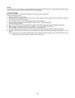
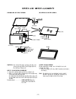
Page 19: ...h a cleaning liquid has been soaked Cleaning liquid LENS LUSTER Manufac tured by Edmund Scientific Co etc HOW TO CLEAN SCREEN When cleaning the screen use a soft cloth so as not to damage the screen 1 Wipe the screen with a dry cloth to remove moisture on the screen Note Absolutely do not use detergent water alcohol benzine thinner etc for cleaning in order not to wipe away the black print on the ...

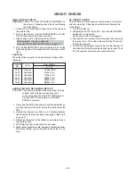
Page 20: ... removing the jumper wire This is the evidence that the FS circuit is functioning properly 4 To obtain a picture again temporarily turn the receiver off and allow the FS circuit more than 5 seconds to reset Then turn the receiver on to produce a normal picture Location No Name 51 57 T461 C440 C443 C444 C467 C468 TFB3094AS 1000pF 3 4700pF 3 3600pF 3 5600pF 5 6800pF 5 ANODE VOLTAGE MEASURING METHOD ...

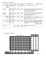
Page 21: ...FF R DRIVE B DRIVE BRIGHT CENTER PICTURE HIT V LINEARITY V S CORRECTION PICTURE WIDTH RCUT BCUT RDRV BDRV BRTC HIT LIN VSC WID Preset Data 80H 80H 40H 40H 80H 30H 12H 29H 48H Table 2 CIRCUIT CHECKS Table 3 Item Name of adjustment Preset Data COLC VCP PARA CNR HCP VFC VCEN TVOP COLOR CENTER V COMPENSATION EW PARABOLA EW M CORRECTION H COMPENSATION V f CORRECTION V CENTERRING TV OPTION 5DH 06H 0FH 1...

Page 22: ... Audio OUT Lift up TouchFocus TV VIDEO EXIT MENU CHANNEL VOLUME VIDEO S VIDEO AUDIO L MONO R Front Remote sensor Behind the screen Video 3 Video audio inputs behind the door TouchFocus MENU TV VIDEO EXIT Volume x Channel zy ANT OUT POWER Power indicator Lift up LOCATION OF CONROLS FRONT REAR ...

Page 23: ...E cycles through the five pictures sizes Natural Theater Wide 1 2 3 and Full FAVORITE allows access to the favorite channel search function MENU allows access to on screen programming menus ENTER sets programming menu information yz x select or adjust programming menus FAV yzcycles through favorite channels CH yz cycles through programmed channels VOL yz adjusts the volume level EXIT exits the pro...

Page 24: ...H PROGRAM Press ENTER to start channel programming The TV will automatically cycle through all the TV or Cable channels depending on which you selected and store all active channels in the channel memory While the TV is cycling through the channels the message Programming Now Please Wait appears When channel programming is complete the message Completed appears Press Channel or to view the program...

Page 25: ...emoval 2 Control Panel Removal 3 Front Mask Removal 4 Shield Plate Lens Removal 5 Mirror Removal 6 Back Board Removal K111 K112 K113 4 screws K601 4 screws A160 CASTER A421 A424 A102 A001 A201 A223 A202 K501 K502 K503 4 screws 10 screws 25 26 ...

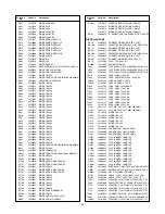
Page 26: ...3 24109473 CERAMIC CHIP 25V B 0 047UF K C324 24503053 PLASTIC FILM 63V 1UF J C325 24082057 PLASTIC FILM 100V 0 22UF J C327 24092730 CERAMIC CHIP 16V B 0 1UF K C328 24082256 PLASTIC FILM 100V 2200PF J C330 24073034 ELECTROLYTIC 16V 10UF M 3A C332 24669101 ELECTROLYTIC 50V 100UF M 3A C333 24082272 PLASTIC FILM 100V 0 047UF J C334 24109471 CERAMIC CHIP 50V B 470PF K C338 24666100 ELECTROLYTIC 10V 10U...

Page 27: ...C 500V B 100PF K C911 24211102 CERAMIC DISC 2KV B 1000PF K C912 24794101 ELECTROLYTIC 16V 100UF M C913 24232103 CERAMIC DISC 50V F 0 01UF Z C914 24109471 CERAMIC CHIP 50V B 470PF K C915 24679220 ELECTROLYTIC 250V 22UF M 3A C917 24214101 CERAMIC DISC 500V B 100PF K C921 24211102 CERAMIC DISC 2KV B 1000PF K C922 24794101 ELECTROLYTIC 16V 100UF M C923 24109471 CERAMIC CHIP 50V B 470PF K C924 24232103...

Page 28: ... 1 20W 3 3K OHM J R373 24011823 CHIP METAL FILM 1 20W 82K OHM J R374 24011104 CHIP METAL FILM 1 20W 100K OHM J R375 24011153 CHIP METAL FILM 1 2OW 15K OHM J R376 24011333 CHIP METAL FILM 1 20W 33K OHM J R378 24011103 CHIP METAL FILM 1 20W 10K OHM J R390 24382561 OXIDE METAL FILM 1W 560 OHM J R391 24382561 OXIDE METAL FILM 1W 560 OHM J R392 24382561 OXIDE METAL FILM 1W 560 OHM J R403 24553101 OXIDE...

Page 29: ... J R843 24376563 CARB0N FILM 1 2W 56K OHM J R844 24011103 CHIP METAL FILM 1 20W 10K OHM J R845 24366102 CARBON FILM 1 6W 1K OHM J R849 24011101 CHIP METAL FILM 1 20W 100 OHM J R854 24381150 OXIDE METAL FILM 1 2W 15 OHM J R860 24383473 OXIDE METAL FILM 2W 47K OHM J R862 24321689 OXIDE METAL FILM 1 2W 6 8 OHM J R864 24552102 OXIDE METAL FILM 1 2W 1K OHM J R865 24552390 OXIDE METAL FILM 1 2W 39 OHM J...

Page 30: ...R7735 24383221 OXIDE METAL FILM 2W 220 OHM J R7736 24339189 METAL FILM 2W 1R8 J R7743 24322338 OXIDE METAL FILM 1W 0 33 OHM J R7744 24322338 OXIDE METAL FILM 1W 0 33 OHM J R7745 24011101 CHIP METAL FILM 1 20W 100 OHM J R7746 24011101 CHIP METAL FILM 1 20W 100 OHM J R7747 24011221 CHIP METAL FILM 1 20W 220 OHM J R7748 24011221 CHIP METAL FILM 1 20W 220 OHM J R7749 24011102 CHIP METAL FILM 1 20W 1K ...

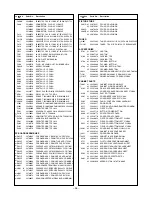
Page 31: ... 22MMH 4 2A TLN3462AH L891 23103145 FERRITE CHOKE TEM2011AA L892 23103145 FERRITE CHOKE TEM2011AA L893 23103145 FERRITE CHOKE TEM2011AA L894 23248247 COIL CHOKE TLN3499AH L895 23248247 COIL CHOKE TLN3499AH L896 23248247 COIL CHOKE TLN3499AH L902 23289159 COIL PEAKING TRF41R5AF L904 23289120 COIL PEAKING TRF4120AF L905 23289689 COIL PEAKING TRF46R8AF L907 23238506 COIL PEAKING TRF4229AJ L911 232892...

Page 32: ...Y QB01 23114528 TRANSISTOR 2SC1740S QH301 23900003 SENSOR PHOTOSENOR SS 2109Y E051Z 23900003 SENSOR PHOTOSENOR SS 2109Y E052Z 23900003 SENSOR PHOTOSENOR SS 2109Y E053Z 23900003 SENSOR PHOTOSENOR SS 2109Y E054Z QV48 23114528 TRANSISTOR 2SC1740S QY160 23205006 TRANSISTOR KTC4075Y D101 23316755 DIODE ZENER MTZJ33C D301 23316581 DIODE ZENER 7 51 7 89 MA8075 H TX D302 23357366 DIODE FR105 B5 D303 23316...

Page 33: ...TO RECEIVER PIC 37043TE2 MISCELLANEOUS BB10 23903022 CONNECTOR BASE B B 8P 2 5 JST BB100 23368627 CONNECTOR BRIDGE B B 8P 2 5JST 08TM 2 5FJ E BB11 23903022 CONNECTOR BASE B B 8P 2 5 JST BB20 23903022 CONNECTOR BASE B B 8P 2 5 JST BB200 23368627 CONNECTOR BRIDGE B B 8P 2 5JST 08TM 2 5FJ E BB21 23903022 CONNECTOR BASE B B 8P 2 5 JST BB60 23713014 CONNECTOR BRIDGE PLUG 16P 1 5 BB70 23713309 PLUG TAC ...

Page 34: ...D ASSY CRT SVM B51HX84 PU PD1733B3 E034Z 23762141 PC BOARD ASSY SVM DIV 51HX84 PU PD1733B4 E051Z 23762004 PC BOARD ASSY CONV SEN PU PD0079B E052Z 23762005 PC BOARD ASSY CONV SEN2 PU PD0079B2 E053Z 23762006 PC BOARD ASSY CONV SEN3 PU PD0079B3 E054Z 23762007 PC BOARD ASSY CONV SEN4 PU PD0079B4 U001 23148103 SCAN CONVERTER MODUL MHSU11 MHSU11 U401 1 23762136 PC BOARD ASSY DEFPOWER 51HX84 PU PD1730D 2...

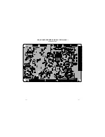
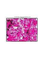
Page 35: ...SCAN CONVERTER MODUL MHSU11 PD1738 U001 BOTTOM FOIL SIDE 36 37 ...

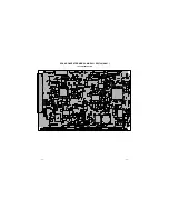
Page 36: ...SCAN CONVERTER MODUL MHSU11 PD1738 U001 TOP COMPONENT SIDE 38 39 ...

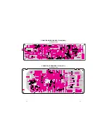
Page 37: ...D412 C420 R423 L852 P405 B802 125V 4A 125V 2A 125V 3A 125V 4A 1 3 B C E R866 L881 C810 T862 SR81 R867 C871 C881 C884 L880 F860 D880 R894 C870 D801 Q843 D883 F851 R810 D884 F852 D895 R487 Q894 L862 SR82 C877 R893 R819 L861 D894 C880 125V 4A B801 125V 4A 1 D879 R860 D873 C866 C876 D876 C802 C869 C809 D878 R872 C860 CAUTION LIVE AREA R418 D418 R419 R417 Q411 R438 R244 R422 R404 Q410 D401 R437 R910 Q2...

Page 38: ... Q664 C601 R616 Q662 Q614 R665 GJ105 D605 R610 D607 D604 C681 D602 D601 D606 D603 R173 GR175 GR601 R174 GR602 23547589 1 14 7 8 B 5 1 18 15 10 5 1 18 15 10 1 2 3 8 7 6 5 4 3 2 GREEN CCP 3400 RED BLUE 8 7 6 5 4 1 1 C7765 D7760 C7750 D7762 R7757 R7750 R7748 R7746 C7786 R7758 R7756 R7751 C7785 Q7763 Q7762 D7766 D7763 D7731 R7880 D7806 C7736 C7784 R7895 C7704 C7701 Q782 C7724 R7887 R7881 R7884 R7755 R...

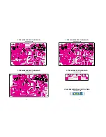
Page 39: ...712 R7122 R7139 Q7105 R7109 R7128 R7135 R7132 R7112 C7106 L7103 R7124 R7105 R7134 R7123 R7136 Q7102 L7104 Q7104 R7106 R7129 R7140 R7125 C7111 C7105 R7130 Q7108 R7117 R7119 R7138 R7113 R7137 Q711 C7101 C7114 Q711A C7103 Q7106 R7121 C7112 3 2 1 R915 R916 C914 Q962 C944 R966 R969 R7103 GJ911 R962 C7104 D961 Q961 R7110 R971 R7104 R967 R9507 R7102 R963 R7111 R918 R7140 R919 R7141 R961 R7131 R987 C7102 ...

Page 40: ...V48 CV27 R265 CV29 BB70 RV40 R287 RV189 QV148 RV161 RV185 CV130 RV34 CV129 LV113 CV127 QB502 23547592 VOL DN MENU POW E B 7 6 5 4 2 1 3 FOCUS TOUCH ANT VIDEO EXIT CH UP CH DN VOL UP RA71 SA04 SA06 DB01 DB01A SA05 RA76 B1 V 0 RB04 RA77 QB01 SA08 PB11 RB05 RB01 RA78 SA07 SA09 RA73 SA01 SA02 RA72 SA03 RA79 23547592 B1 V 0 2 CV14 PV60 S701 PV05 RV22 RV21 RV23 LV20 P701 RV20 5 1 2 3 4 6 7 9 10 8 3 1 23...

Page 41: ...A1788 2SA1306 2SA1186A 2SC752GTM 2SC2482 2SC2655 2SC4721P 2SC752 2SA562TM 2SA1015 2SC1815 2SC2878 2SC1740S 2SC2120 2SA9335 2SA1788 RN2203 RN2201 RN2004 RN1203 RN1204 RN2204 RN1205 RN1202 RN1201 2SD1554 2SD2253 2SD1556 2SD2553 2SC5143 E C B B C E BCE B CE B C E E C B E C B ON4409 B C E ...

Page 42: ... 000 All resistors are 1 6W and 5 tolerance carbon resistor unless otherwise noted as the following marks 1 2R Metal or Metal oxide of 1 2 watt 1 2S Carbon compsistion of 1 2 watt 1RF Fuse resistor of 1 watt 10W Cement of 10 watt K 10 G 2 F 1 2 CAPACITOR Unless otherwise noted in schematic all capacitor values less than 1 are expressed in µF and the values more than 1 in pF All capacitors are cera...

Page 43: ... 8 56 60 CONVER REG Circuit 1 4 SHEET 1 4 57 60 2 4 SHEET 2 4 58 60 3 4 SHEET 3 4 59 60 4 4 SHEET 4 4 60 60 G HYPER Circuit 1 3 SHEET 1 3 32 60 2 3 SHEET 2 3 33 60 3 3 SHEET 3 3 34 60 GNESIS Circuit 1 3 SHEET 1 3 42 60 2 3 SHEET 2 3 43 60 3 3 SHEET 3 3 44 60 AD CONVERTER Circuit A SHEET 1 3 35 60 B SHEET 2 3 36 60 C SHEET 3 3 37 60 GC TC90A92A Circuit 1 3 SHEET 1 3 38 60 2 3 SHEET 2 3 39 60 GC TC9...

Page 44: ... 51 52 CIRCUIT BLOCK DIAGRAM ...

Page 45: ...UDIO 150 mV rms 22 k ohms or more VIDEO AUDIO OUTPUT VIDEO 1 V p p 75 ohms negative sync AUDIO 150 mV rms 30 modulation equivalent 2 2 k ohms or less VARIABLE AUDIO OUTPUT 0 300 mV rms 30 modulation equivalent 2 2 k ohms or less Specifications Design and specifications are subject to change without notice Video Audio Terminals cont HDMI INPUT HDMI 1 0 compliant type A connector HDCP 1 1 compliant ...

Page 46: ...TOSHIBA CORPORATION 1 1 SHIBAURA 1 CHOME MINATO KU TOKYO 105 8001 JAPAN ...

Reviews: