37
5
Applied Control and Functions
(Including Circuit Configuration)
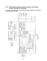
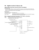
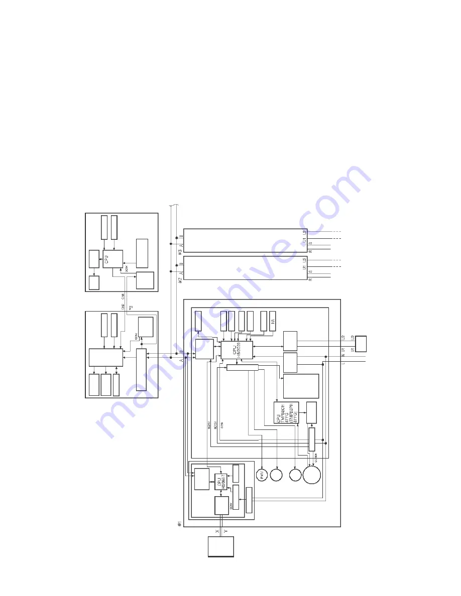
5-1. Indoor controller block diagram
5-1-1. When main (sub) remote controller connected
<Compact 4-way cassette type, 1-way cassette (SH) type, ceiling type, concealed duct
standard type, slim duct type>
Main (
s
ub)
remote controller
(
up t
o
2
units)
Main remote controlle
r
:RB
C-AMT3
2
E
Sub r
e
mote c
ont
ro
ller
:RB
C-AS
21
E
2
Sche
dule Ti
mer (Wee
kly
time
r mode)
D
is
pl
ay
LC
D
D
is
pl
ay
LE
D
EEP
R
O
M
Remo
te
co
nt
ro
lle
r
comm
u
n
ica
tion cir
cu
it
Funct
io
n set
ting
Po
w
e
r
sup
ply
cir
cu
it
R
e
cha
rgea
bl
e
ba
tter
y
D
isp
la
y
LCD
L
CD
dr
iv
er
Funct
ion set
tin
g
K
e
y switch
Ke
y swi
tc
h
CP
U
Po
we
r
su
pply
circuit
Indoor unit
Ce
ntra
l
re
m
o
te
con
tr
o
ll
e
r
(o
p
ti
on
al
)
Net
wo
rk
a
dapt
or
(
opt
iona
l)
Ind
oo
r con
tro
l P.C. bo
a
rd (M
CC-1
40
2
)
(In ca
se
o
f 1:
1
m
ode
l)
Network
ad
ap
tor
P.C
.
bo
ar
d
(MCC
-14
0
1
)
Remot
e c
ont
ro
lle
r
co
m
m
un
icat
ion
circ
ui
t
AI
-N
ET
co
m
m
unic
ation
cir
cuit
Po
wer
s
uppl
y
cir
cui
t
Sw
itch
se
ttin
g
Tran
s
for
mer
Lo
uv
er
mo
to
r
In
do
or
fa
n
mo
to
r
*N
ot
ap
plic
ab
le
to
c
on
ceale
d d
uc
t
st
an
dar
d t
ype
S
lim
D
uc
t T
yp
e
Drai
n
pu
m
p
P
ower
supp
ly
ci
rc
ui
t
F
an m
o
to
r
co
nt
rol
c
irc
ui
t
In
op
erat
io
n
Al
arm
Get
ti
ng ready
T
her
m
o
stat
ON
COOL
HEAT
FAN
AC
synchr
oni
zat
ion
si
gnal
input
ci
rc
ui
t
BU
S
co
mmu
ni
ca
tio
n
ci
rc
ui
t
E
x
tern
al
ou
tpu
t
Driver
T
A
s
ens
or
T
C
I s
ens
or
T
C
2 s
ens
or
T
C
J
s
ens
or
F
loat
input
Remote
co
nt
ro
lle
r
communi
cati
on
ci
rc
ui
t
EE
PR
O
M
N
e
tw
o
rk
ada
pto
r :
"1
:1
mo
de
l"
co
nn
ecti
on
i
n
te
rf
ace
T
C
B-
PCN
T
3
0
T
LE
2
In
do
o
r / o
u
td
oo
r c
o
mmu
nic
a
tion
P
o
wer so
urce
1
Ø
22
0-
24
0 V
, 50
H
z
1
Ø
22
0
V, 6
0
Hz
Out
d
oor
uni
t
Sam
e
as lef
t
*2
Sam
ea
s left
*2
Pow
e
r
sou
rce
Up
to
8 u
n
its ca
n b
e
conn
ecte
d.
*1
*1
Only u
p
to 7 un
its if
a
n
e
two
rk
ad
a
p
to
r is insta
lle
d with
2
ma
in
(su
b
) r
e
m
o
te
co
nt
ro
lle
rs
co
nne
cte
d.
*2
The
net
wor
k
a
d
a
p
to
r ca
n on
ly
be
in
sta
lle
d in
on
e u
n
it
.
*3
A w
e
ekl
y
ti
m
e
r cann
ot
be
co
nne
cte
d to
a
sub
re
mote
con
tro
lle
r.
Po
we
r
sou
rc
e
Ou
tdo
or
un
it
Outd
oo
r
uni
t
Summary of Contents for A03-009
Page 149: ...148 ...
Page 153: ...152 9 2 1 Way cassette type SH AP015 AP018 AP024 ...
Page 161: ...160 9 4 Slim duct type MMD AP0074SPH AP0094SPH AP0124SPH AP0154SPH AP0184SPH ...
Page 165: ...164 9 5 Concealed duct standard type MMD AP0074BH AP0094BH AP0124BH AP0154BH AP0184BH ...
Page 166: ...165 ...
Page 169: ...168 MMD AP0244BH AP0274BH AP0304BH AP0364BH AP0484BH ...
Page 170: ...169 ...
Page 173: ...172 MMD AP0564BH ...
Page 174: ...173 ...
Page 177: ...176 E Parts ...
Page 179: ...178 9 6 Concealed duct high static pressure type MMD AP0184H AP0244H AP0274H AP0364H AP0484H ...
Page 183: ...182 MMD AP0724H AP0964H ...
Page 184: ...183 ...
Page 187: ...186 9 7 Ceiling type MMC AP0154H AP0184H AP0244H AP0274H ...
Page 190: ...189 MMC AP0364H AP0484H ...
Page 194: ...193 9 8 Floor standing type MMF AP0154H AP0184H AP0244H AP0274H ...
Page 195: ...194 MMF AP0154H AP0184H AP0244H AP0274H ...
Page 198: ...197 MMF AP0364H AP0484H AP0564H ...
Page 199: ...198 MMF AP0364H AP0484H AP0564H ...
Page 203: ...202 9 9 Floor standing concealed type MML AP0074BH AP0094BH AP0124BH AP0154BH AP0184BH ...
Page 206: ...205 MML AP0244BH ...
Page 209: ...208 9 10 Floor standing cabinet type MML AP0074H AP0094H AP0124H AP0154H AP0184H ...
Page 210: ...209 MML AP0074H AP0094H AP0124H AP0154H AP0184H ...
Page 213: ...212 MML AP0244H ...
Page 214: ...213 MML AP0244H ...


