background image

– 

22

 –

FILE NO. SVM-0

4007

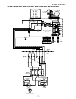
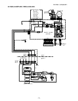
6. CONTROL BLOCK DIAGRAM

6-1. RAS-24UKHP-ES

3

, RAS-18UKHP-ES

3

 / RAS-24UKHP-AS

3

, RAS-18UKHP-AS

3

REMOTE CONTROL

Indoor Unit Control Panel

Heat Exchanger Sensor

Temperature Sensor

Infrared Rays Signal Receiver

Initiallizing Circuit

Clock Frequency

Oscillator Circuit

Power Supply

Circuit

Noise Filter

From Outdoor Unit

220 ~ 240V AC 50Hz

M.C.U.

Functions

•  

 Louver Control

•  

 3-minute Delay at Restart for Compressor

• 

  Motor Revolution Control

•  

 Processing

•  

 Timer

•  

 Serial Signal Communication

Louver ON/OFF Signal

Louver Driver

Serial Signal Transmitter/Receiver 

Serial Signal Communication

Operation

Display

Timer

Display

Filter Sign

Display

PRE DEF.

Sign Display

Indoor 

Fan Motor

Hi Power

Sign Display

Louver Motor

Infrared

Rays

Remote

Control

(Temperature Processing)

Remote Control

Operation (START/STOP)

Operation Mode Selection 

AUTO, COOL, DRY, HEAT, FAN ONLY

Temperature Setting

Fan Speed Selection

ON TIMER Setting

OFF TIMER Setting

Louver Auto Swing

Louver Direction Setting

ECO

Hi power

Filter Reset

Infrared Rays

• 


20 sec Self Cleaning Function

Summary of Contents for AS-24UKHP-ES3

Page 1: ...3 RAS 24UAH ES3 RAS 18UKHP ES3 RAS 18UAH ES3 RAS 24UKP ES3 RAS 24UA ES3 RAS 18UKP ES3 RAS 18UA ES3 18 Class Heat pump model 24 Class 18 Class Cooling only model RAS 24UKHP AS3 RAS 24UAH AS3 RAS 18UKHP AS3 RAS 18UAH AS3 RAS 24UKP AS3 RAS 24UA AS3 RAS 18UKP AS3 RAS 18UA AS3 May 2004 ...

Page 2: ...RAS 18UKP AS3 4 5 Outdoor Unit RAS 24UA ES3 RAS 24UA AS3 4 6 Outdoor Unit RAS 18UA ES3 RAS 18UA AS3 5 REFRIGERATION CYCLE DIAGRAM 5 1 RAS 24UKHP ES3 RAS 24UAH ES3 RAS 24UKHP AS3 RAS 24UAH AS3 5 2 RAS 18UKHP ES3 RAS 18UAH ES3 RAS 18UKHP AS3 RAS 18UAH AS3 5 3 RAS 24UKP ES3 RAS 24UA ES3 RAS 24UKP AS3 RAS 24UA AS3 5 4 RAS 18UKP ES3 RAS 18UA ES3 RAS 18UKP AS3 RAS 18UA AS3 6 CONTROL BLOCK DIAGRAM 6 1 RA...

Page 3: ...T 10 1 Indoor Unit 10 2 Outdoor Unit RAS 24UAH ES3 RAS 24UA ES3 RAS 24UAH AS3 RAS 24UA AS3 10 3 Outdoor Unit RAS 18UAH ES3 RAS 18UAH AS3 10 4 Outdoor Unit RAS 18UA ES3 RAS 18UA AS3 11 EXPLODED VIEWS AND PARTS LIST 11 1 Indoor Unit E Parts Assy 11 2 Indoor Unit 11 3 Outdoor Unit RAS 24UAH ES3 RAS 24UAH AS3 11 4 Outdoor Unit RAS 18UAH ES3 RAS 18UAH AS3 11 5 Outdoor Unit RAS 24UA ES3 RAS 24UA AS3 11 ...

Page 4: ...mum height m 8 difference INDOOR UNIT RAS 24UKHP ES3 RAS 24UKP ES3 RAS 18UKHP ES3 RAS 18UKP ES3 Height mm 298 Dimensions Width mm 998 Depth mm 208 Net weight kg 12 Evaporator type Finned tube Indoor fan type Cross flow fan High fan m3 h 950 950 950 750 800 750 Air volume Medium fan m3 h 750 800 750 650 700 650 Low fan m3 h 600 650 600 530 570 530 Fan motor output W 20 Air filter Honeycomb woven fi...

Page 5: ...onnection type Flare connection Liquid side size mm 6 35 Interconnection Connection type Flare connection pipe Maximum length m 15 1 One way 25 2 20 2 Maximum height m 8 difference INDOOR UNIT RAS 24UKHP AS3 RAS 24UKP AS3 RAS 18UKHP AS3 RAS 18UKP AS3 Height mm 298 Dimensions Width mm 998 Depth mm 208 Net weight kg 12 Evaporator type Finned tube Indoor fan type Cross flow fan High fan m3 h 950 950 ...

Page 6: ...P ES3 RAS 18UA ES3 1 No need to charge 15m or less 15m or less extra refrigerant 2 Need to charge Over 15m up to 25m 20g m Over 15m up to 20m 20g m extra refrigerant Temperature Condition JIS C9612 1994 Cooling Heating Indoor unit inlet air temperature DB 27 C 20 C WB 19 C 15 C Outdoor unit inlet air temperature DB 35 C 7 C WB 24 C 6 C RAS 24UKHP AS3 RAS 24UAH AS3 RAS 24UKP AS3 RAS 24UA AS3 RAS 18...

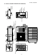
Page 7: ...5 7 51 100 40 48 450 20 20 48 100 6 5 998 298 10 763 5 55 55 55 41 29 57 18 160 6 5 8 Back body Knock out system Front panel Grille inlet Knock out system Connection pipe 0 39m Flare 12 7 Connection pipe 0 49m Wireless remote control Flare 6 35 For stud bolt 6 Drain hose 0 54m Installation Plate outline Outline of indoor unit ...

Page 8: ...itch 12 12 364 A 12x18 hole A Detail Drawing 25 Drain outlet 52 Handle Installation dimension 600 100 or more 100 or more 600 or more 600 or more Air outlet Air inlet Electric Parts cover Liquid side Flare 6 35 Gas side Flare 12 7 Service Port 600 340 23 68 Handle 4 12X18 for 8 10 anchor bolt RAS 24UAH AS3 RAS 24UA AS3 ...

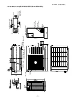
Page 9: ...outdoor unit 6 11x14 holes or 8 10 anchor bolt Fan guard 420 Electric Parts cover Liquid side Flare 6 35 Gas side Flare 12 7 Installation dimension 100 or more Air inlet 600 or more 100 or more Air inlet Air outlet 600 or more 600 50 35 4x 11x14 for 8 10 anchor bolt 600 344 325 91 54 60 50 90 600 830 90 120 52 23 325 Handle 538 300 Service Port ...

Page 10: ...door unit A 325 120 4 11x14 hole for Ø8 Ø10 anchor bolt Liquid side Flare 6 35 Gas side Flare 12 7 52 5 Service Port Electric parts cover 344 27 130 100 Installation dimension 100 or more Air inlet 600 or more 100 or more Air inlet Air outlet 600 or more 4x 11x14 or 8 10 anchor bolt 600 325 23 301 325 11x14 hole 6 hole R10 600 Detail Drawing 50 35 A ...

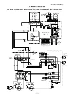
Page 11: ...06 IC01 IC T01 IC04 C15 CN23 BLK WHI RED GRN YEL CN30 CN31 C01 R01 R09 R21 R22 BLK P04 SG01 DSA VARISTOR T6 3A 250V IC02 DISCHARGE PIPE SENSOR TD HEAT EXCHANGER SENSOR TE CN08 CN07 BLU BLU BLK BLK 1 1 2 3 3 1 1 2 3 3 DC15V DC0V DC12V DC7V DC0V 3 1 2 i L N 3 1 2 i FERRITE CORE GRN YEL RED RED BLK BLK MAGNETIC CONTACTOR R A1 A2 52C U S V T W PNK WHI COMPRESSOR TERMINAL BLK S R C WHI BLK BLK COIL FOR...

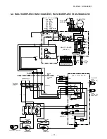
Page 12: ... C02 C06 IC01 IC T01 IC04 C15 CN23 BLK WHI RED GRN YEL CN30 CN31 C01 R01 R09 R21 R22 BLK P04 SG01 DSA VARISTOR T6 3A 250V IC02 DISCHARGE PIPE SENSOR TD HEAT EXCHANGER SENSOR TE CN08 CN07 BLU BLU BLK BLK 1 1 2 3 3 1 1 2 3 3 DC15V DC0V DC12V DC7V DC0V 3 1 2 i L N 3 1 2 i FERRITE CORE GRN YEL RED RED BLK BLK MAGNETIC CONTACTOR R A1 A2 52C U S V T W PNK WHI COMPRESSOR TERMINAL BLK S R C WHI BLK BLK CO...

Page 13: ...01 CN25 CN13 BLK BLK BLK BLK F01 FUSE RY04 DB01 FAN MOTOR LOUVER MOTOR MAIN P C BOARD MCC 821 L01 BLU BLU BLU BLU BLU BLU BLU BLU WHI DC MOTOR CN 07 CN 10 C02 C06 IC02 IC01 IC T01 IC04 C15 BLK WHI GRN YEL RED C01 R01 R09 R21 R22 BLK P04 SG01 DSA VARISTOR T6 3A 250 V DC15V DC0V DC12V DC7V DC0V CN30 CN31 CN27 GREEN GRN YELLOW 3 1 2 L N 3 1 2 GRN YEL RED RED RED RED BLK BLK CHASSIS GRY POWER SUPPLY 2...

Page 14: ...A 1 2 1 2 1 2 1 2 CN03 CN01 CN25 CN13 BLK BLK BLK BLK F01 FUSE DB01 FAN MOTOR LOUVER MOTOR MAIN P C BOARD MCC 821 L01 BLU BLU BLU BLU BLU BLU BLU BLU WHI DC MOTOR CN 07 CN 10 C02 C06 IC02 IC01 IC T01 IC04 C15 BLK WHI GRN YEL RED CN30 CN31 CN27 C01 R01 R09 R21 R22 BLK P04 SG01 DSA VARISTOR T6 3A 250 V DC15V DC0V DC12V DC7V DC0V RY04 3 1 2 L N 3 1 2 GRN YEL RED RED GRY RED BLK BLK BLK BLK GRN YEL CH...

Page 15: ... BLK F01 FUSE RY04 DB01 FAN MOTOR LOUVER MOTOR MAIN P C BOARD MCC 821 L01 BLU BLU BLU BLU BLU BLU BLU BLU WHI DC MOTOR CN 07 CN 10 C02 C06 IC02 IC01 IC T01 IC04 C15 BLK WHI GRN YEL RED C01 R01 R09 R21 R22 BLK P04 DSA T6 3A 250 V SG01 VARISTOR DC15V DC0V DC12V DC7V DC0V CN30 CN31 CN27 GREEN GRN YELLOW 3 1 2 L N 3 1 2 GRN YEL RED RED BLK RED RED RED BLK BLK CHASSIS GRY POWER SUPPLY 220 240 V 50 Hz S...

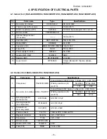
Page 16: ...r R01 RF 5TK4R7B 4 7Ω 5W 13 Louver motor MP35EA12 Output Rated 2W 10poles 4phase DC 12V 4 2 Outdoor Unit RAS 24UAH ES3 RAS 24UAH AS3 No Parts name Type Specifications Output Rated 2200W 2poles 1 phase 220 240V 50Hz 1 Compressor PA290X3F 4MS Winding resistance Ω Red Black White Black at 20 C 1 07 2 20 Output Rated 65W 6poles 1 phase 220 240V 50Hz 2 Fan motor for outdoor KFG6 71SB5P T1 Winding resis...

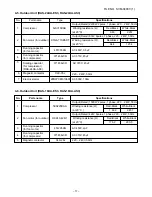
Page 17: ...rmer TT 05 220 240V 9 Microcomputer TMP47C840N 10 Varistor R73 R74 15G471K 470V 11 Fuse F01 TSCR T6 3A 250V 4 4 Indoor Unit RAS 24UKP ES3 RAS 18UKP ES3 RAS 24UKP AS3 RAS 18UKP AS3 No Parts name Type Specifications 1 Fan motor for indoor ICF 340 30 2 DC 340V 30W 2 Thermo sensor TA sensor 10kΩ at 25 C 3 DC DC transformer T01 SWT 58A DC 390V Secondary DC 15V 12V 7V 4 Microcontroller TMP87CM40AN 5 Hea...

Page 18: ...compressor 5 Starting capacitor for compressor RAS 24UA AS3 371456JCR AC 370V 45µF 6 Magnetic contactor CLK 35J 220 240V 50Hz 7 Electric starter ZPR0YCE101A500 AC 500V 100Ω 4 6 Outdoor Unit RAS 18UA ES3 RAS 18UA AS3 No Parts name Type Specifications Output Rated 1500W 2poles 1 phase 220 240V 50Hz 1 Compressor 5KS225DAA Winding resistance Ω Red Black White Black at 20 C 1 632 2 457 Output Rated 42W...

Page 19: ...11 0 High 27 19 35 24 Cooling Overload 0 8 12 0 High 32 23 43 26 Low temperature 0 5 1 0 Low 21 15 21 15 Standard pressure P MPaG Surface temp of heat exchanger interchanging pipe T1 C Fan speed indoor 50Hz Heat exchanger Indoor unit Cross flow fan Cooling Heating 4 way valve Heating Cooling Compressor Condenser Propeller fan Outdoor unit PA290X3F 4MS Cooling Heating Mark means check points of Gas...

Page 20: ... 27 19 35 24 Cooling Overload 1 0 15 0 High 32 23 43 26 Low temperature 0 6 1 0 Low 21 15 21 15 Fan speed indoor 50Hz Standard pressure P MPaG Surface temp of heat exchanger interchanging pipe T1 C Indoor unit Cross flow fan Cooling Heating 4 way valve Heating Cooling Compressor Condenser Propeller fan Outdoor unit PA225X3F 4L Cooling Heating Mark means check points of Gas Leak O D 12 7mm O D 6 35...

Page 21: ... Fan speed indoor 50Hz Standard pressure P MPaG Surface temp of heat exchanger interchanging pipe T1 C Heat exchanger Indoor unit Cross flow fan Cooling Cooling Compressor Condenser Propeller fan Outdoor unit 5JS315DAG01 Cooling Mark means check points of Gas Leak O D 12 7mm O D 6 35mm Cooling Packed valve Gas container connection Reinstall etc 12 7 Packed valve 6 35 0 49m Connecting pipe 12 7 0 3...

Page 22: ... 0 6 2 0 Low 21 15 21 15 Fan speed indoor 50Hz Standard pressure P MPaG Surface temp of heat exchanger interchanging pipe T1 C Indoor unit Cross flow fan Cooling Cooling Compressor Condenser Propeller fan Outdoor unit 5KS225DAA Cooling Mark means check points of Gas Leak O D 12 7mm O D 6 35mm Cooling Packed valve 12 7 Packed valve 6 35 0 39m Connecting pipe 12 7 0 49m Connecting pipe 6 35 T1 P Ref...

Page 23: ...Motor Revolution Control Processing Timer Serial Signal Communication Louver ON OFF Signal Louver Driver Serial Signal Transmitter Receiver Serial Signal Communication Operation Display Timer Display Filter Sign Display PRE DEF Sign Display Indoor Fan Motor Hi Power Sign Display Louver Motor Infrared Rays Remote Control Temperature Processing Remote Control Operation START STOP Operation Mode Sele...

Page 24: ...r Control 3 minute Delay at Restart for Compressor Motor Revolution Control Processing Timer Louver ON OFF Signal Louver Driver Operation Display Timer Display Filter Sign Display Fan Only Sign Display Indoor Fan Motor Hi Power Sign Display Louver Motor Infrared Rays Remote Control Temperature Processing REMOTE CONTROL Remote Control Operation START STOP Operation Mode Selection AUTO COOL DRY FAN ...

Page 25: ...oller The outdoor unit controller receives operation commands from the indoor unit and operates the outdoor fan motor and the compressor 1 Role of indoor unit controller The indoor unit controller receives the operation commands from the remote control and executes them Temperature measurement at the air inlet of the indoor heat exchanger by the indoor temperature sensor Temperature setting of the...

Page 26: ...r flow NOTE 1 The values marked with 1 are calculated and controlled by the difference in motor speed between M and L Fig 7 2 1 Setting of air flow FAN AUTO 2 ECO operation cannot be set 7 2 2 Cooling operation MODE button on the remote control is set to the cooling operation 1 The compressor 4 way valve outdoor fan and operation display lamp are controlled as shown in Fig 7 2 2 Fig 7 2 2 2 When F...

Page 27: ...mp are controlled as shown in Fig 7 2 4 Fig 7 2 4 2 The microprocessor turns the compressor on and off at the regular intervals 4 to 6 minutes While the compressor is turning off the indoor fan motor operates in the SUPER LOW position The pattern of operation depending on the relation between room temperature and preset temperatures is shown in Fig 7 2 5 Fig 7 2 5 3 FAN button on the remote contro...

Page 28: ...oling Fan only or Heating is selected according to difference between the preset temperature and the room temperature at which the automatic operation has started as shown in Fig 7 2 9 The Fan only operation continues until the room temperature reaches a level at which another mode is selected 2 Temporary Auto When the TEMPORARY button on the indoor unit is pushed the preset temperature is fixed a...

Page 29: ...eset temperature is higher 2 C 4 The Hi POWER mode can not be set in Dry or Fan only operation 7 4 High Temperature Limit Control Heat pump model only The microcontroller detects the indoor heat exchanger temperature to prevent pressure of a refrigerating cycle from increasing excessively The compressor and outdoor fan motor are controlled as shown in Fig 7 4 1 Fig 7 4 1 7 5 Low Temperature Limit ...

Page 30: ...o restart function proceed as follows The power supply to the unit must be on the function will not set if the power is off Push the TEMPORARY button located in the center of the front panel continuously for three seconds The unit receives the signal and beeps three times The unit then restarts operating automatically in the event of power supply being accidentally shut down While the filter check...

Page 31: ... to turn off filter check lamp Press FILTER button on the remote control OR push TEMPORARY button on the indoor unit Note If TEMPORARY button is pushed while the filter check lamp is not indicating the indoor unit will start the Automatic Operation Operation Motions Push TEMPORARY button for more The unit is on standby than three seconds The unit starts to operate The orange lamp is on After appro...

Page 32: ...O RESTART function had been cancelled To set AUTO RESTART again please follow item 7 7 1 7 9 2 How to set Self Cleaning function To set the Self Cleaning function proceed as follows Press TEMPORARY button one time or use remote control to turn on air conditioner The OPERATION display will show in orange color When AUTO RESTART is ON or green color When AUTO RESTART is OFF Hold down the TEMPORARY b...

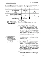
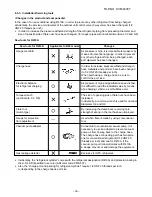
Page 33: ...re also required Accordingly special tools are required for the new refrigerant R410A as shown below For connecting pipes use new and clean piping materials with high pressure withstand capabilities designed for R410A only and ensure that water or dust does not enter Moreover do not use any existing piping as its pressure withstand may be insufficient and may contain impurities New Refrigerant Air...

Page 34: ...roperly earthed Appliance shall be installed in accordance with national wiring regulations If you detect any damage do not install the unit Contact your TOSHIBA dealer immediately CAUTION Exposure of unit to water or other moisture before installation could result in electric shock Do not store it in a wet basement or expose to rain or water After unpacking the unit examine it carefully for possi...

Page 35: ...ng Insert the cushion between the indoor unit and wall and lift the indoor unit for better operation Wall The auxiliary piping can be connected the left rear left rear right or bottom Insulate the refrigerant pipes separately with insulation not together 6 mm thick heat resisting polyethylene foam Left Rear left Right Rear Bottom Attach to the front panel Attach to the air filter 6 Zeolite filter ...

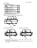
Page 36: ...o a strong wind Use 8 mm or 10 mm anchor bolts and nuts If it is necessary to drain the defrost water attach drain nipple Š to the bottom plate of the outdoor unit before installing it Part Code A B C Q ty One each 1 One each Parts name Refrigerant piping Liquid side 6 35 mm Gas side 12 7 mm Pipe insulating material polyethylene foam 6 mm thick Putty PVC tapes Air inlet Drain outlet 600 mm 120 mm ...

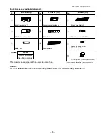
Page 37: ...t No 4 5 6 Part No 7 8 9 Others Name Owner s manual Installation manual The part marked with asterisk is packaged with the outdoor unit This model is not equipped with an extension drain hose Option For the extension drain hose use an optionally available RB 821SW or commercially available one Part name Q ty Bioenzyme filter x 2 Mounting screw 4 x 25 s x 8 Pan head wood screw 3 1 x 16 s x 2 Drain ...

Page 38: ...rigerant from being charged each port diameter has been changed Charge hose In order to increase pressure withstand strength hose materials and port size have been changed to 1 2 UNF 20 threads per inch When purchasing a charge hose be sure to confirm the port size Electronic balance As pressure is high and gasification speed is fast for refrigerant charging it is difficult to read the indicated v...

Page 39: ...arest TV set or stereo equipment This is necessary to prevent image disturbances or noise interference The location of the remote control should be determined as shown below Fig 8 4 1 5 m 5 m 45 45 75 7 m 7 m Top view Indoor unit Axial distance Reception range Reception range Remote control Indoor unit Remote control Side view 8 4 2 Cutting a hole and mounting installation plate Cutting a hole Whe...

Page 40: ...ult in personal injury and property damage if the unit falls In case of block brick concrete or similar type walls make 5 mm dia holes in the wall Insert clip anchors for appropriate mounting screws 8 NOTE Secure four corners and lower parts of the installation plate with 6 to 8 mounting screws to install it Installation plate Keep horizontal direction 8 4 3 Electrical work 1 The supply voltage mu...

Page 41: ...nnecting cable with the cord clamp 8 Fix the terminal cover rear plate bushing and air inlet grille on the indoor unit Front panel Earth line Connecting cable 2 1 Cord clamp Terminal block Screw Terminal cover Screw Air Inlet grille CAUTION Be sure to refer to the wiring system diagram labeled inside the front panel Check local electrical cords and also any specific wiring instructions or limitati...

Page 42: ...n the wall After passing the connecting pipe through the pipe hole connect the connecting pipe to the auxiliary pipes and wrap the facing tape around them CAUTION Bind the auxiliary pipes two and connecting cable with facing tape tightly In case of leftward piping and rear leftward piping bind the auxiliary pipes two only with facing tape Carefully arrange pipes so that any pipe does not stick out...

Page 43: ...m Drain hose Shield pipe Extension drain hose Wall Drain guide Space for pipes Do not put the drain hose end in the drainage ditch Do not form the drain hose into a wavy shape Do not put the drain hose end into water Do not rise the drain hose 50 mm or more 8 4 6 Indoor unit fixing 1 Pass the pipe through the hole in the wall and hook the indoor unit on the installation plate at the upper hooks 2 ...

Page 44: ... a duct or a wind shield 3 In particularly windy areas install the unit such as to avoid admission of wind 4 Installation in the following places may result in trouble Do not install the unit in such places A place full of machine oil A saline place such as the coast A place full of sulfide gas A place where high frequency waves are likely to be generated as from audio equipment welders and medica...

Page 45: ...oth side of Gas and Liquid 7 Remove the charging hose from the service port 8 Securely tighten the caps on the packed valves Fig 8 5 6 Tightening torque of flare pipe connections The operating pressure of R410A is higher than that of R22 Approx 1 6 times It is therefore necessary to firmly tighten the flare pipe connecting sections which connect the indoor and outdoor units up to the specified tig...

Page 46: ...e connecting cable to the outdoor unit terminal make a loop as shown in the installation diagram of indoor and outdoor unit to prevent water coming in the outdoor unit 4 Insulate the unused cords conductors from any water coming in the outdoor unit Proceed them so that they do not touch any electrical or metal parts Stripping length of connecting cable Fig 8 5 8 CAUTION Wrong wiring connection may...

Page 47: ...nd Front panel Refer to page 63 10 1 3 Select the terminal of selector switch from A position to B position Fig 8 6 1 2 Set the remote control selector switch with the remote control B is indicated on the liquid crystal display when setting remote control selector switch to B A is not indicated on the display even if the selector switch is set to A 1 Load the remote control with the batteries 2 Pr...

Page 48: ...connections Indoor unit Valve stem cap connection TEMPORARY button D C A B 8 7 3 Auto restart setting This product is designed so that after a power failure it can restart automatically in the same operating mode as before the power failure Information The product was shipped with Auto Restart function in the off position Turn it on as required How to set the auto restart Press and hold the TEMPOR...

Page 49: ...rned on 8 The operation mode changes in the Automatic operation 9 The Fan only operation continues in the Automatic operation 10 The ECO operation or Hi POWER operation does not work 11 When Hi POWER button is pressed the display on the remote control does not change at all No Operation of air conditioner Descriptions The OPERATION lamp blinks to indicate that power is turned on If the START STOP ...

Page 50: ...z E OPERATION lamp is blinking 5Hz F OPERATION and TIMER lamps are blinking 5Hz G OPERATION TIMER and PRE DEF or FAN ONLY for cooling only model lamps are blinking Table 9 3 2 Diagnosis by detective operation The remote control does not work The outdoor fan does not rotate Turn off the power supply once then turn it on Try to operate the remote control The compressor operates The compressor does n...

Page 51: ...with a code the indoor unit will beep once Pi and the display of the remote control will change as follows Check the unit with all 35 check codes 00 to 22 as shown in Table 9 4 1 Press TIMER 9 button to change the check code backwards If there is a fault the indoor unit will beep for 10 seconds Pi Pi Pi Note the check code on the display of the remote control 2 digits alphanumeric will be indicate...

Page 52: ...m errors The lamp on the indoor unit blinks when error is defected The lamp on the indoor unit blinks when error is defected The lamp on the indoor unit blinks when error is defected And it returns to the normal condition when recovering from errors The lamp on the indoor unit blinks when error is defected The lamp on the indoor unit blinks when error is detected 1 Check the indoor thermo sensor T...

Page 53: ...ect crossover wires properly Connect connector properly Indoor P C board is defective Replace P C board Operation Check item Conceivable principle cause Measure Item by symptoms Does four way valve operate properly Does coil terminal have 220 240 V in heating operation Are circuit wires normal Is outdoor P C board normal Four way valve is defective Outdoor P C board is defective CN11 220 240V Indo...

Page 54: ... Outdoor P C board is defective Indoor P C board is defective Is TC sensor resistance value 10kΩ at 25 C normal Failure 09 Other cycle error 1 Heat pump model 09 Other cycle error 2 Clean filters Replace TC sensor Charge refrigerant Replacd P C board Anti freezing operation Anti freezing operation Does indoor fan operate Are filters clogged Is charged amount of refrigerant normal Is outside air lo...

Page 55: ...e Connect CN04 properly Replace TA sensor Replace P C board NO NO YES YES Is CN05 TC sensor connector connected properly Is TC sensor resistance value 10 kΩ at 25 C normal Indoor P C board is defective Connect CN05 properly Replace TC sensor Replace P C board NO NO YES YES Is TE sensor connector connected properly Is TE sensor resistance value 10 kΩ at 25 C normal Indoor P C board is defective Con...

Page 56: ...y Replace TD sensor Replace P C board NO NO NO YES NO YES YES NO YES Is protective controller such as discharge thermostat normal Is charged amount of refrigerant normal Is overload relay normal Is TD sensor resistance value 50 kΩ at 25 C normal Are wires connected to connector properly Outdoor P C board is defective Connect wires to connector properly Check and modify charged amount of refrigeran...

Page 57: ...tor Is voltage DC 12V or 5V indicated on rear of indoor control board normal Is fuse F01 of indoor control board blown Parts R21 R22 SG01 C15 C01 DB01 C02 IC01 and T01 are defective Are DC 15V DC 12V or DC 7V supplied to secondary side of transfer switch Transfer switch IC IC01 for power supply or fan motor is defective Replace motor Does the fan motor connector between 1 and 2 short circuit Micro...

Page 58: ...etween 4e and 3d of motor connector CN10 Start to operate the indoor unit in except heating operation At this time is it possible to detect DC 1V or more between 5e and 3d of motor connector CN10 Is it possible to rotate cross flow fan by hand properly Turn off indoor unit and rotate cross flow fan by hand when the unit is on standby At this time is it possible to detect DC 1V or more between 5e a...

Page 59: ...ws 2 Remove the cover of the fan motor lead wires 3 Check DC voltage with CN10 connector while the fan motor is rotating NOTE Do not disconnect the connector while the fan motor is rotating Use a thin test rod DC P C board CN10 6 Blue 5 Yellow 4 White 3 Black 2 1 Red Black Yellow Indoor fan starts rotating when power supply is turned on Check output DC voltage of fan motor on P C board Measure vol...

Page 60: ...sor does not operate Primary check 1 Is the preset temperature higher than the room temperature in cooling operation 2 Is the crossover cable connected properly Inspection procedure Cooling only model FILE NO SVM 04007 ...

Page 61: ...r winding normal Check winding resistor NO Compressor is defective YES Replace compressor Is capacitor for compressor normal NO Capacitor is defective Is it possible to detect AC 200V between 2 and 3 on terminal block Is crossover cable normal YES Is overload relay normal Does compressor start Does compressor stop after a while Is gas quantity normal Check gas pressure Compressor is defective Repl...

Page 62: ... 60 Inspection procedure Heating model Replace transformer FILE NO SVM 04007 AC 70 100V outdoor P C board ...

Page 63: ... compressor motor winding normal Check winding resistor Is gas quantity normal Check gas pressure Is capacitor for compressor normal Is overload relay normal Does compressor start Does compressor stop after a while Replace compressor Compressor is defective Compressor is defective NO Capacitor is defective NO Overload relay is defective NO Compressor is defective NO Gas shortage Gas leak FILE NO S...

Page 64: ...e unit 2 1 3 Terminal block on indoor side Terminal block Tester Red White 2 The outdoor unit stops once it would not operate until the power is turned on again 3 The outdoor unit stops between 10 minutes to 1 hour after starting and a check code is indicated on the remote control Check code 03 1E Refer to Table 9 4 1 Measure gas pressure Gas shortage Pipe clogging Compressor is turned off and on ...

Page 65: ...L01 resistor R01 or the diode DB01 is defective 3 IC01 IC02 and T01 are defective 4 IC01 IC02 and T01 are defective 5 IC01 IC02 IC07 and T01 are defective Heat pump model IC05 and IC06 are defectice Cooling only model 1 The wire of the relay coil RY04 comes down or the relay drive Q33 is defective 2 CN27 or RY04 is connected wrongly The lamps are defective or the housing assembly CN13 is defective...

Page 66: ... exchanger sensor and the P C board are defective Refer to Table 9 8 2 4 The main P C board is defective 1 The temperature of the indoor heat exchanger is extremely high 2 The connector of the heat exchanger sensor short circuited CN01 3 The heat exchanger sensor and the P C board are defective Refer to Table 9 8 2 4 The main P C board is defective 1 The indoor fan motor is defective Protected ope...

Page 67: ... 65 FILE NO SVM 04007 Top View Bottom View 9 8 3 P C Board layout ...

Page 68: ...ate Remote control is defective Does indoor unit start to operate by automatic restart function Does radio sound is affected by remote control when a signal is transmitted at distance of 5 cm from radio P C board is defective Keep indoor unit away from thyristor fluorescent light Avoid direct sunlight Replace P C board Replace batteries Normal operation Replace remote control The unit does not bee...

Page 69: ...let 3 Check the gap between the front panel and the back body If you operate the air conditioner in cooling or dry operation without pushing the 3 places the surface of the front panel may be covered with frost and have dewdrops 1 Remove the front panel with the procedure 1 2 Remove the screw fixing the electrical part box 3 Remove the drain guide 4 Remove the connector 5P for the fan motor and th...

Page 70: ... exchanger with procedure 4 2 Loosen the set screw of the cross flow fan 3 Remove 2 screws fixing the bearing base and the back body 4 Pull the cross flow fan toward you 1 Remove the front panel electrical parts assembly horizontal grille heat exchanger and the cross flow fan with procedure 5 2 Remove the bearing from the bearing base If the housing protrudes from the base bearing put the housing ...

Page 71: ...screws 4 x 10L 3 Disconnect the lead wires from the terminal 1 Perform the common procedure 1 2 Remove the fixing screw 2 screws 4 x 10L 3 Disconnect the housing from the P C Board 1 Perform the common procedure 1 2 Disconnect the lead wires from the P C Board 3 Remove P C Board after unhooking 4 clams 1 Perform the common procedure 1 2 Remove the fixing screw 1 screw 4 x 10L 3 Disconnect the lead...

Page 72: ...nnect the lead wires from the terminal No Part name Procedures Remarks FILE NO SVM 04007 70 Running capacitor for compressor Spark killer Starting capacitor for compressor Electric starter Magnetic contactor RAS 24UA AS3 Running capacitor for fan motor Electric starter 8 RAS 24UA AS3 ...

Page 73: ...t the lead wires from the capacitor terminal 1 Perform the common procedure 1 2 Remove the fixing screw 1 screw 4 x 10L 3 Disconnect the lead wires from the capacitor terminal 1 Perform the common procedure 1 2 Remove the fixing screw 2 screws 4 x 10L 3 Disconnect the lead wires from the relay terminal 1 Perform the common procedure 1 2 Remove the fixing screw 2 screws 4 x 10L 3 Disconnect the hou...

Page 74: ...on procedure 1 2 Remove the capacitor band 1 screw 4 x 10L 3 Disconnect the lead wires from the capacitor terminal 1 Perform the common procedure 1 2 Remove the fixing screw 1 screw 4 x 10L 3 Disconnect the lead wires from the capacitor terminal 1 Perform the common procedure 1 2 3 Disconnect the lead wires from the relay terminal 1 Perform the common procedure 1 2 Remove the fixing screw 1 screw ...

Page 75: ...300V 20A 403 43T50004 Sensor Heat Exchanger 10k 25 C 404 43T69005 Sensor Thermostat 10k 25 C 405 43T69066 P C Board ASSY WRS LED MCC 819 406 43T69375 P C Board ASSY RAS 24UKHP ES3 AS3 Location Part Description No No 406 43T69376 P C Board ASSY RAS 24UKP ES3 AS3 406 43T69377 P C Board ASSY RAS 18UKHP ES3 AS3 406 43T69378 P C Board ASSY RAS 18UKP ES3 AS3 407 43T62003 Clamp Cord ...

Page 76: ...o 222 43T49037 Holder Plate EVA Seal 223 43T79007 Guide Drain 224 43T39016 Fix Motor 225 43T60075 Fan Motor Cord 226 43T21327 Motor Fan 227 43T20014 Fan Cross Flow 228 43T22002 M Bearing ASSY 229 43T39015 Base Bearing 230 43T03013 Back Body ASSY 231 43T07022 Holder Pipe 232 43T82007 Plate Installation 233 43T85410 Owner s Manual All model 233 43T85412 Owner s Manual RAS 18 24UKP ES3 234 43T69310 R...

Page 77: ...sor PA290X3F 4MS 19 43T62014 Protector Cord 20 43T62015 Protector Cord 21 43T49011 Base Spring A Location Part Description No No 22 43T49012 Base Spring B 23 43T49019 Spring Buffer 24 43T21315 Motor Fan AC 220 240V 50Hz 25 43T20301 Fan Propeller 491 26 43T96001 Bushing 27 43T96004 Bushing Cord 28 43T62013 Cover E Parts 29 43T52301 Switch Magnet CLK 35J 220 24V 50Hz 30 43T55316 MF Capacitor 45µF 37...

Page 78: ... Condenser Assembly 15 43T46317 Valve Packed 6 35Dia 16 43T47020 Bonnet 6 35Dia 17 43T46318 Valve Packed 12 7Dia 18 43T47018 Bonnet 12 7Dia Location Part Description No No 19 43T47308 Capillary Tube 1 0Dia 20 43T47014 Capillary Tube 1 7Dia 23 43T49008 Cushion Rubber 24 43T55316 MF Capacitor 45µF 370V 25 43T55318 MF Capacitor 2µF 450V 26 43T60324 Terminal Block 6P 27 43T41311 Compressor PA225X3F 4L...

Page 79: ...net 6 35Dia 15 43T47013 Capillary Tube 2 0Dia 16 43T60324 Terminal Block 6P 18 Compressor 5JS315DAG01 19 43T62014 Protector Cord 20 43T62015 Protector Cord Location Part Description No No 24 43T21314 Motor Fan AC 220 240V 50Hz 25 43T20301 Fan Propeller 491 26 43T96001 Bushing 27 43T96004 Bushing Cord 28 43T62013 Cover E Parts 29 43T52301 Switch Magnet CLK 35J 30 43T55316 MF Capacitor 45µF 370V 31 ...

Page 80: ... 43T47013 Capillary Tube 2 0Dia 16 43T60324 Terminal Block 6P 18 Compressor 5JS315DAG01 19 43T62014 Protector Cord 20 43T62015 Protector Cord Location Part Description No No 24 43T21314 Motor Fan AC 220 240V 50Hz 25 43T20301 Fan Propeller 491 26 43T96001 Bushing 27 43T96004 Bushing Cord 28 43T62013 Cover E Parts 29 43T52301 Switch Magnet CLK 35J 30 43T55316 MF Capacitor 45µF 370V 31 43T55317 MF Ca...

Page 81: ...43T47001 Nut Flange 12 43T63004 Clamp Lead Wire 13 43T96001 Bushing 14 Condenser Assembly 15 43T46317 Valve Packed 6 35Dia 16 43T47020 Bonnet 6 35Dia Location Part Description No No 17 43T46318 Valve Packed 12 7Dia 18 43T47018 Bonnet 12 7Dia 19 43T47014 Capillary Tube 1 7Dia 22 43T49008 Cushion Rubber 24 43T55316 MF Capacitor 45µF 370V 25 43T55318 MF Capacitor 2µF 450V 26 43T60324 Terminal Block 6...

Page 82: ... 75 FILE NO SVM 03009 1 TOSHIBA CARRIER THAILAND CO LTD 144 9 MOO 5 BANGKADI INDUSTRIAL PARK TIVANON ROAD TAMBOL BANGKADI AMPHUR MUANG PATHUMTHANI 12000 THAILAND ...

Reviews: