2-9
EM18-33010A
2. MAJOR UNIT REPLACEMENT
Strip Shaft
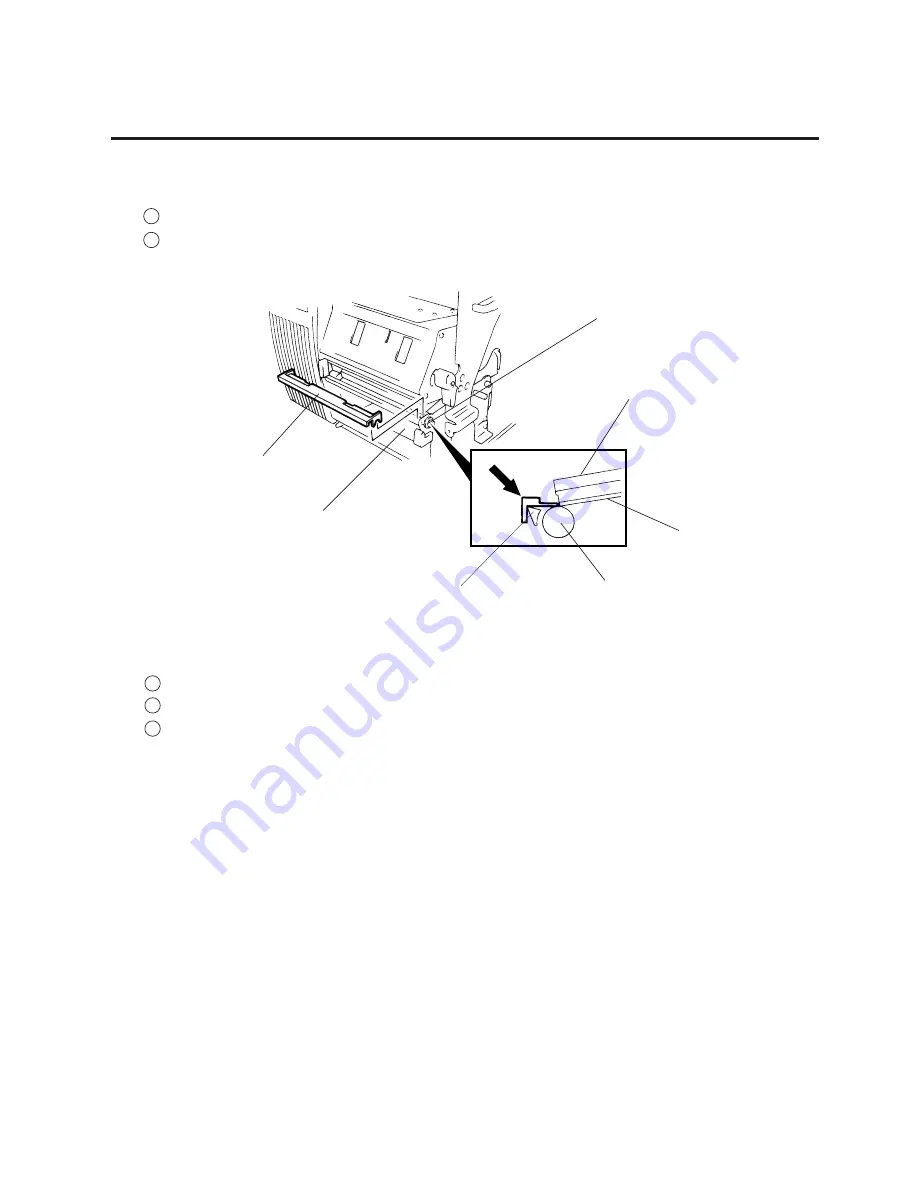
Fig. 2-14
(Revision Date Feb. 01, ’96)
2.6 REPLACING THE PRINT HEAD
■
Adjusting the print head position
1
Fit the jig in the platen and strip shaft.
2
Press the jig at an angle of 45
°
until it is sung against the print head. Then secure the print head.
3
Remove the jig.
4
Refer to page 6-43 and clear the maintenance counter.
5
Refer to page 6-31 and perform test print.
NOTE: Use caution to prevent damage to the element during adjustment of the print head.
Platen
Ceramic
Print Head
Platen
Strip Shaft
Jig
Summary of Contents for B-570
Page 3: ......
Page 4: ...PRINTED IN JAPAN EO0 33004 ...
Page 5: ...TEC Thermal Printer B 570 QQ SERIES Owner s Manual ...
Page 33: ......
Page 34: ...PRINTED IN JAPAN EM1 33035 E ...
Page 56: ......
Page 57: ......
Page 58: ...PRINTED IN JAPAN EM10 33006A ...
Page 157: ......
Page 158: ...PRINTED IN JAPAN EM18 33010A ...


