3-8
EM18-33010A
3. INSTALLATION PROCEDURE FOR THE OPTIONAL EQUIPMENT
3.
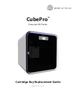
Remove the FL-4x5 screw to detach the blind plate on the back of the printer and attach the fanfold
paper guide (rear) with the same screw.
(Revision Date: Feb. 10, 2000)
3.4 FANFOLD PAPER GUIDE MODULE (B-4905-FF-QM)
3.4 FANFOLD PAPER GUIDE MODULE (B-4905-FF-QM)
1.
Open the top cover.
2.
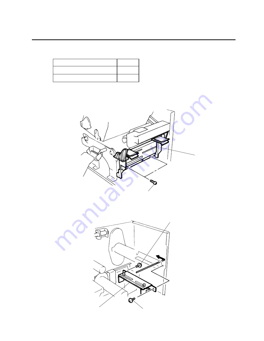
Remove the T-4x8 screws to detach the paper guide ass’y at the center of the printer and attach the
fanfold paper guide (front) with these same screws.
Description
Fanfold Paper Guide(rear)
Fanfood Paper Guide (front)
Q’ty/Unit
1
1
Fig. 3-11
Fig. 3-12
Screw (T-4x8)
Fanfold Paper Guide
(front)
Screw (FL-4x5)
Screw (FL-4x5)
Fanfold Paper Guide (rear)
Summary of Contents for B-570
Page 3: ......
Page 4: ...PRINTED IN JAPAN EO0 33004 ...
Page 5: ...TEC Thermal Printer B 570 QQ SERIES Owner s Manual ...
Page 33: ......
Page 34: ...PRINTED IN JAPAN EM1 33035 E ...
Page 56: ......
Page 57: ......
Page 58: ...PRINTED IN JAPAN EM10 33006A ...
Page 157: ......
Page 158: ...PRINTED IN JAPAN EM18 33010A ...


