2. PRINTER SETUP
ENGLISH VERSION EO1-33055
2.9 Setting an Operating Environment
E2-18
2.9.1 Parameter
Setting
(Cont.)
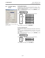
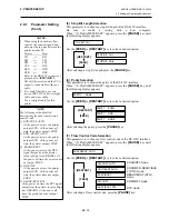
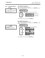
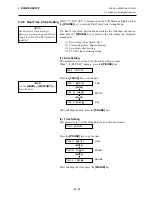
(5) Stop Bit Length Selection
This parameter is to choose a stop bit length of the RS-232C interface.
Be sure to match a setting with a host computer.
When “<2>PARAMETER SET” appears, press the
[PAUSE]
key until
the following display appears.
Use the
[FEED]
or
[RESTART]
key to select a desired option.
After selecting a stop bit length, press the
[PAUSE]
key.
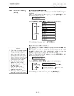
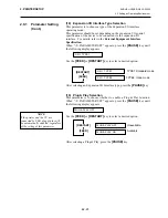
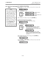
(6) Parity Selection
This parameter is to choose the parity of the RS-232C interface.
When “<2>PARAMETER SET” appears, press the
[PAUSE]
key
until
the following display appears.
Use the
[FEED]
or
[RESTART]
key to select a desired option.
After selecting the parity, press the
[PAUSE]
key.
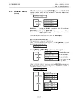
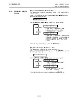
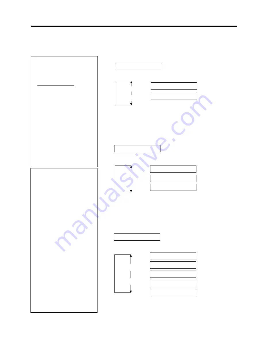
(7) Flow Control Code Selection
This parameter is to choose a flow control code of the RS-232C interface.
When “<2>PARAMETER SET” appears, press the
[PAUSE]
key until
the following display appears.
Use the
[FEED]
or
[RESTART]
key to select a desired option.
After selecting a flow control code, press the
[PAUSE]
key.
STOP BIT 1bit
STOP BIT 2bits
STOP BIT 1bit
[RESTART]
[FEED]
XON+READY AUTO
[RESTART]
[FEED]
XON+READY AUTO
XON/XOFF AUTO
READY/BUSY
XON/XOFF
READY/BUSY RTS
XON/XOFF mode
XON/XOFF+READY/BUS
Y (DTR) mode
READY/BUSY (DTR)
mode
XON/XOFF mode
RTS mode
PARITY NONE
PARITY EVEN
PARITY ODD
[RESTART]
[FEED]
PARITY NONE
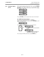
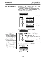
NOTE:
The following is the detailed
descriptions for each transmission
control code.
1) XON/XOFF AUTO
At the power on time, the printer
outputs XON. At the power off
time, the printer outputs XOFF.
2) XON+READY AUTO
At the power on time, the printer
outputs XON. At the power off
time, the printer outputs XOFF.
3) READY/BUSY
At the power on time, the DTR
signal output from the printer
turns to High level (READY). At
the power off time, the printer does
not output XOFF.
4) ON/XOFF
At the power on time, the printer
outputs XON. At the power off
time, the printer does not output
XOFF.
5) READY/BUSY RTS
At the power on time, the RTS signal
output from the printer turns to High
level (READY). At the power off
time, the printer does not output
XOFF.
NOTES:
1. When using the hardware flow
control, the control signals and
data must be in pairs between the
printer and the PC.
Printer Host
TD
→
RD
RD
←
- TD
RTS
→
CTS
CTS
←
- RTS
DSR
→
DTR
DTR
←
- DSR
Refer to the RS-232C connector’s
pin layout in APPENDIX 2.
Check if the printer and the PC is
properly connectable with your
cable
2. Be careful that there are two
types of RS-232C cable; straight
cable and cross cable.
Use a straight cable for this
printer.

