- 5 -
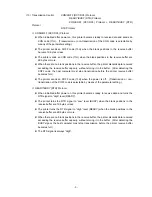
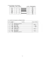
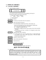
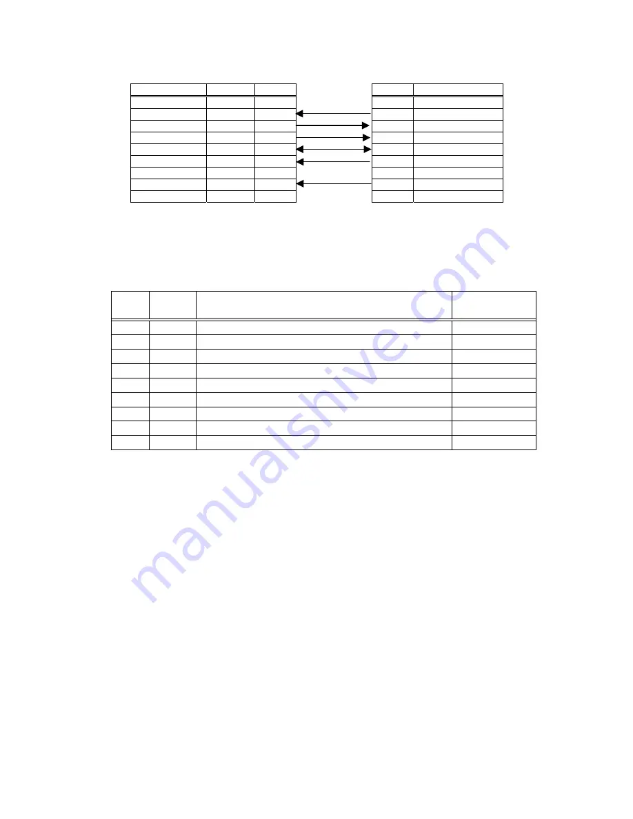
(14) RS-232 Interface pin configuration
Host Function
9 Pin
25 Pin
9 Pin
Printer Function
1
+5V
RxD
2
3 2 TxD
TxD
3
2 3 RxD
DTR 4
20 4 DSR
GND
5
7 5 GND
DSR
6
6 6 RDY
RTS
7
4 7 N/C
CTS
8
5 8 RDY
9
+5V
(15) Connector Pin Assignment and Signal Description
Pin No.
Signal
Name
Function Signal
Direction
1
+5V
Provide the power of 5V
2 TxD
Transmit
data
Printer
→
3 RxD
Receive
data
←
Host
4
DSR
Data set ready
←
Host
5 GND
General
Ground
6 RDY
Printer
ready
Printer
→
7 N/C
Not
connected
8 RDY
Printer
ready
Printer
→
9
+5V
Provide the power of 5V
Summary of Contents for B-EV4 Series
Page 232: ... 228 3 JIS Hexadecimal ...
Page 233: ... 229 ...
Page 234: ... 230 ...
Page 235: ... 231 ...
Page 236: ... 232 ...
Page 237: ... 233 ...
Page 238: ... 234 11 7 TrueType FONT 1 PC 850 2 PC 8 ...
Page 239: ... 235 3 PC 852 4 PC 857 ...
Page 240: ... 236 5 PC 851 6 PC 855 ...
Page 241: ... 237 7 PC 1250 8 PC 1251 ...
Page 242: ... 238 9 PC 1252 10 PC 1253 ...
Page 243: ... 239 11 PC 1254 12 PC 1257 ...


