3. REPLACING THE IMPORTANT PARTS
EO18-33030
3.1 Replacing the Parts for B-FV4T-GS/TS
3-5
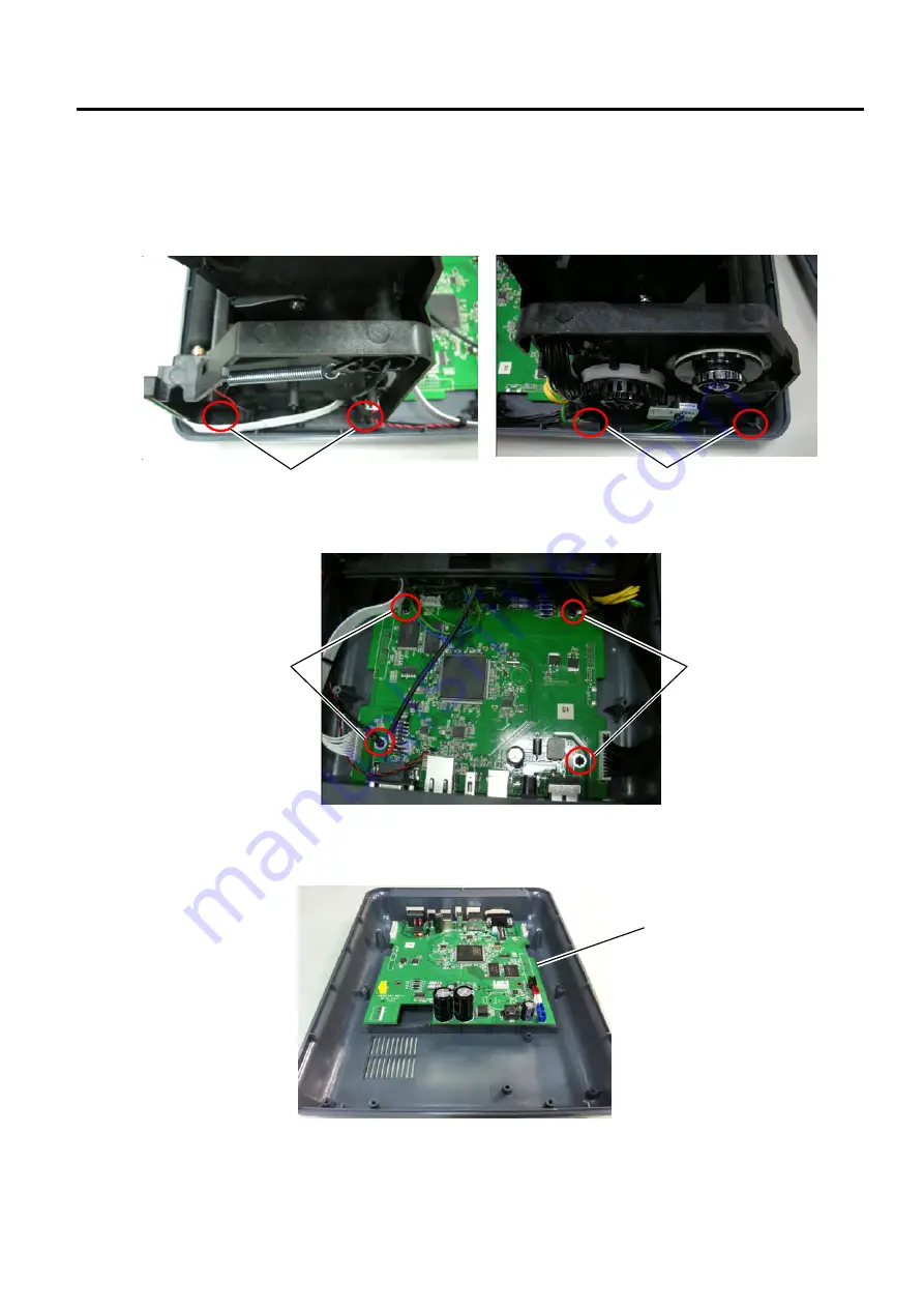
3.1.2 Replacing the Main PC Board
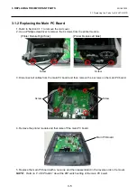
1. Refer to Section 3.1.1 to remove the mid cover.
2. Use a Phillips screwdriver to remove the 4 screws from the printer module.
3. Disconnect all cables from the main PC board and then remove the 4 screws on the main PC board.
4. Remove the printer module and then take off the main PC board.
5. Replace the main PC board with a new one and then reassemble it in the reverse order of removal.
NOTE:
Refer
to
“
2.4 DIP Switch
”
about the DIP switch setting of the main PC board.
Screw
Screw
Screw
Main PC Board
[Printer Module Right Side]
[Printer Module Left Side]
Screw
Summary of Contents for B-FV4 Series
Page 41: ...2 ELECTRONICS SPECIFICATIONS EO18 33030 2 2 Main PC Board Layout 2 4 B FV4D GH B FV4D GL ...
Page 301: ...APPENDIX EO18 33030 APPENDIX Establishing a Bluetooth connection with B FV4D and B FV4T A 8 ...
Page 302: ...1 11 1 OSAKI SHINAGAWA KU TOKYO 141 8562 JAPAN E PRINTED IN JAPAN EO18 33030H ...


