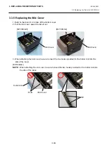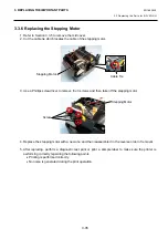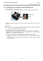
3. REPLACING THE IMPORTANT PARTS
EO18-33030
3.2 Replacing the Parts for B-FV4D-GS/TS
3-21
3.2.6 Replacing the Media Sensor [Feed Gap Senor (Lower) / Black Mark
Sensor]
1. Refer to Section 3.2.5 to remove the stepping motor.
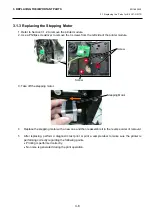
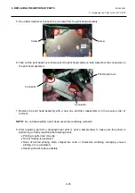
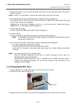
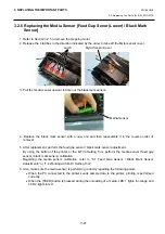
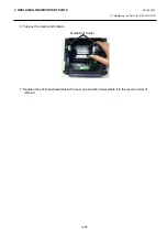
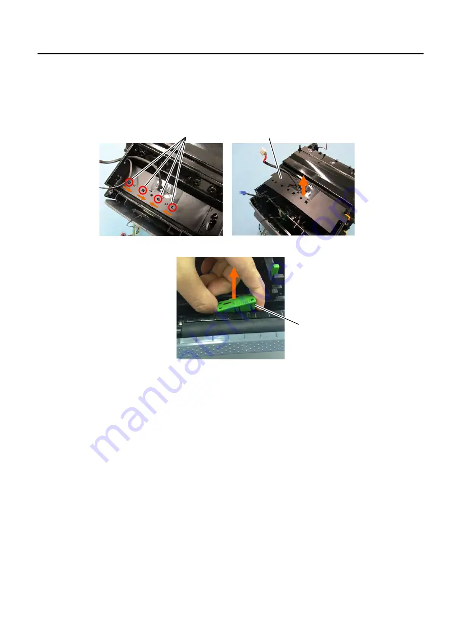
2. Release the 4 latches in the direction indicated by the arrow to take off the Mylar sensor cover.
3. Pull the media sensor upward to take out the black mark sensor.
4. Replace the black mark sensor with a new one and then reassemble it in the reverse order of
removal.
5. After replacement, perform the feed gap sensor / black mark sensor adjustment.
By using the button of the printer or the B-FV4 Setting Tool, perform the media sensor (feed gap
sensor / black mark sensor) calibration.
Regarding the media sensor calibration, refer to “6.1 Feed Gap Sensor / Black Mark Sensor
Adjustments” or “7.2 Working with B-FV Setting Tool”.
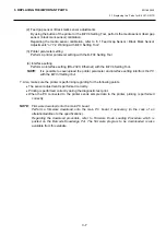
6. Also, make sure the media sensor is performing correctly regarding the following points.
When the PC connected to the printer sends sample data to the printer, printing is performed
correctly.
When the [FEED] button is pressed during the unloading of a media, LED 1 lights in orange and
LED 2 lights in red.
Latch
Media Sensor
Mylar Sensor Cover
Summary of Contents for B-FV4 Series
Page 41: ...2 ELECTRONICS SPECIFICATIONS EO18 33030 2 2 Main PC Board Layout 2 4 B FV4D GH B FV4D GL ...
Page 301: ...APPENDIX EO18 33030 APPENDIX Establishing a Bluetooth connection with B FV4D and B FV4T A 8 ...
Page 302: ...1 11 1 OSAKI SHINAGAWA KU TOKYO 141 8562 JAPAN E PRINTED IN JAPAN EO18 33030H ...

