3. REPLACING THE IMPORTANT PARTS
EO18-33030
3.2 Replacing the Parts for B-FV4D-GS/TS
3-22
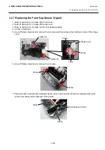
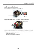
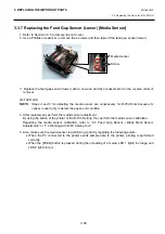
3.2.7 Replacing the Feed Gap Sensor (Upper)
1. Refer to Section 3.2.4 to take off the mid cover.
2. Refer to Section 3.2.1 to take off the top cover.
3. Refer to Section 3.2.9 to take out the print head assembly.
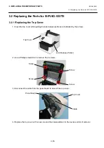
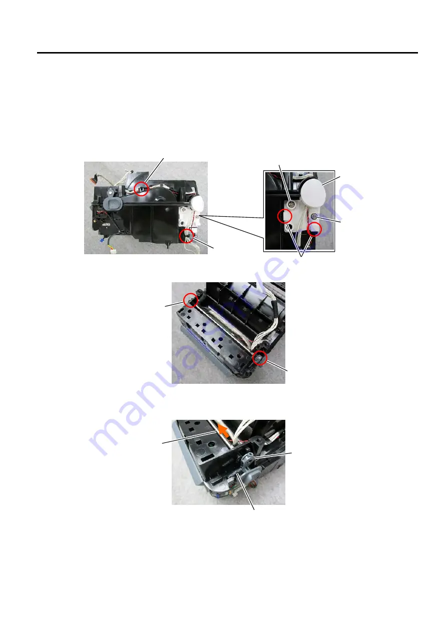
4. Cut the 2 cable ties.
5. Use a Phillips screwdriver to remove the 2 screws and then release the 2 latches to take off the hinge
cover.
6. Use a Phillips screwdriver to remove the 2 screws.
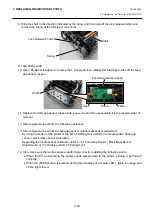
7. Slide the shaft in the direction indicated by the arrow and then take off the lock release portion and
remove the spring at the right side of the printer.
Cable Tie
Cable Tie
Screw
Screw
Lock Release Portion
Spring
Shaft
Latch
Screw
Screw
Hinge Cover
Summary of Contents for B-FV4 Series
Page 41: ...2 ELECTRONICS SPECIFICATIONS EO18 33030 2 2 Main PC Board Layout 2 4 B FV4D GH B FV4D GL ...
Page 301: ...APPENDIX EO18 33030 APPENDIX Establishing a Bluetooth connection with B FV4D and B FV4T A 8 ...
Page 302: ...1 11 1 OSAKI SHINAGAWA KU TOKYO 141 8562 JAPAN E PRINTED IN JAPAN EO18 33030H ...

