3-10
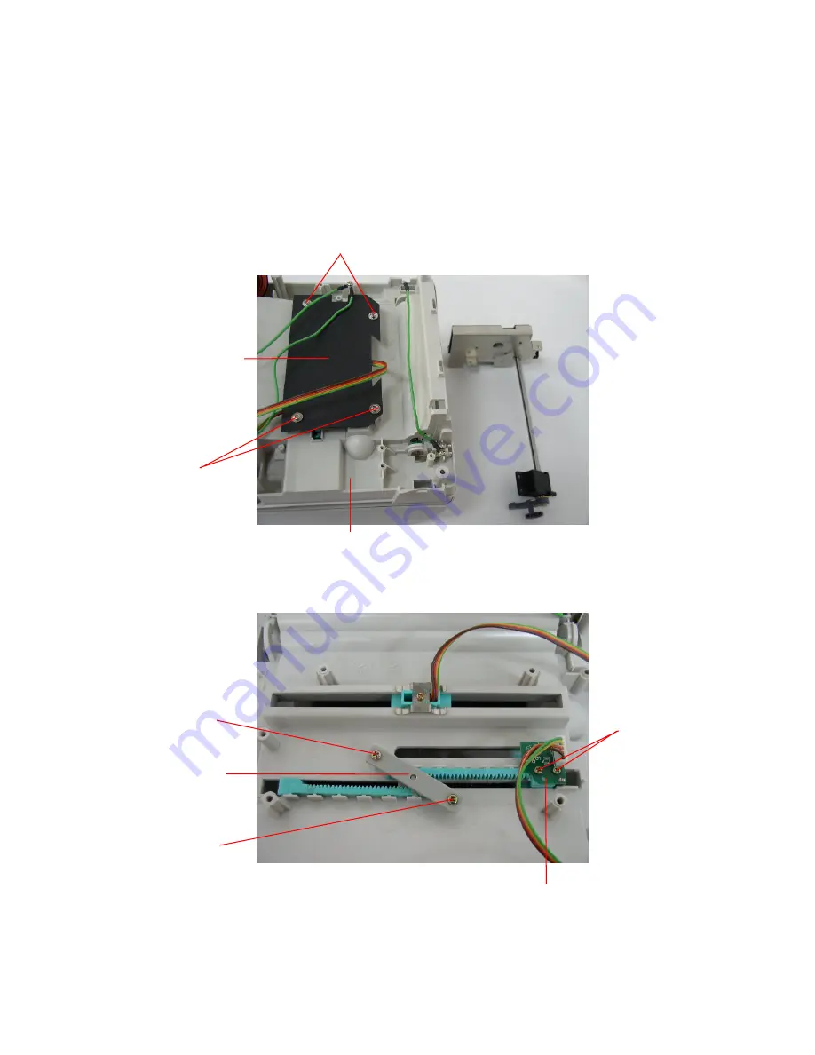
3.7 Replacing the Feed Gap Sensor Ass’y and Label Guide
1. Please refer to 3.1 for disassembling the lower cover ass’y and lower inner
cover.
2. Disconnect all harnesses from the main PCB ass’y .
3. Turn the lower inner cover upside down.
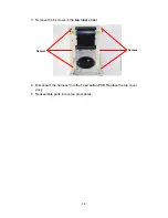
4. Screws off 4 screws and remove the
plastic laminate
.
5. Screws off 2 screws from a Label Guide Rack Fixing Plate and 2 from a gap
sensor PCB then remove the
feed gap sensor ass’y
.
Screws
Screws
Screw
Screw
Feed Gap Sensor Ass’y
Plastic Laminate
Lower Inner Cover
Label Guide
Rack Fixing
Plate
Screw
Summary of Contents for B-SV4T
Page 15: ...2 3 2 2 MCU Circuit and MCU PIN Description Fig 5 MCU PIN Description Diagram ...
Page 16: ...2 4 2 2 1 MCU PIN Description ...
Page 17: ...2 5 ...
Page 18: ...2 6 ...
Page 19: ...2 7 ...
Page 23: ...2 11 2 5 Decoder Circuit Fig 8 Decode Circuit Diagram ...
Page 32: ...2 20 2 12 USB Circuit Fig 14 USB Circuit Diagram ...
Page 33: ...2 21 2 12 1 USB PIN Function The standard USB 1 1 PIN function is as following ...
Page 34: ...2 22 ...
Page 46: ...3 6 4 Replace the main PCB ass y 5 Reassemble parts in reverse procedures ...
Page 59: ...4 2 4 Revert the memory module cover 5 Reassemble parts in reverse procedures ...
Page 71: ...E PRINTED IN JAPAN EO18 33019 ...


