background image

Touch Screen Controller

Owner's Manual

88

-EN

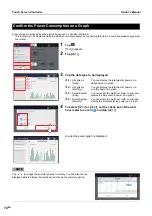
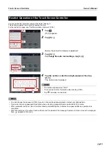
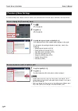
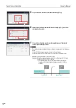
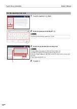
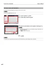
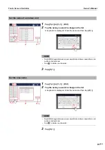
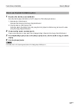
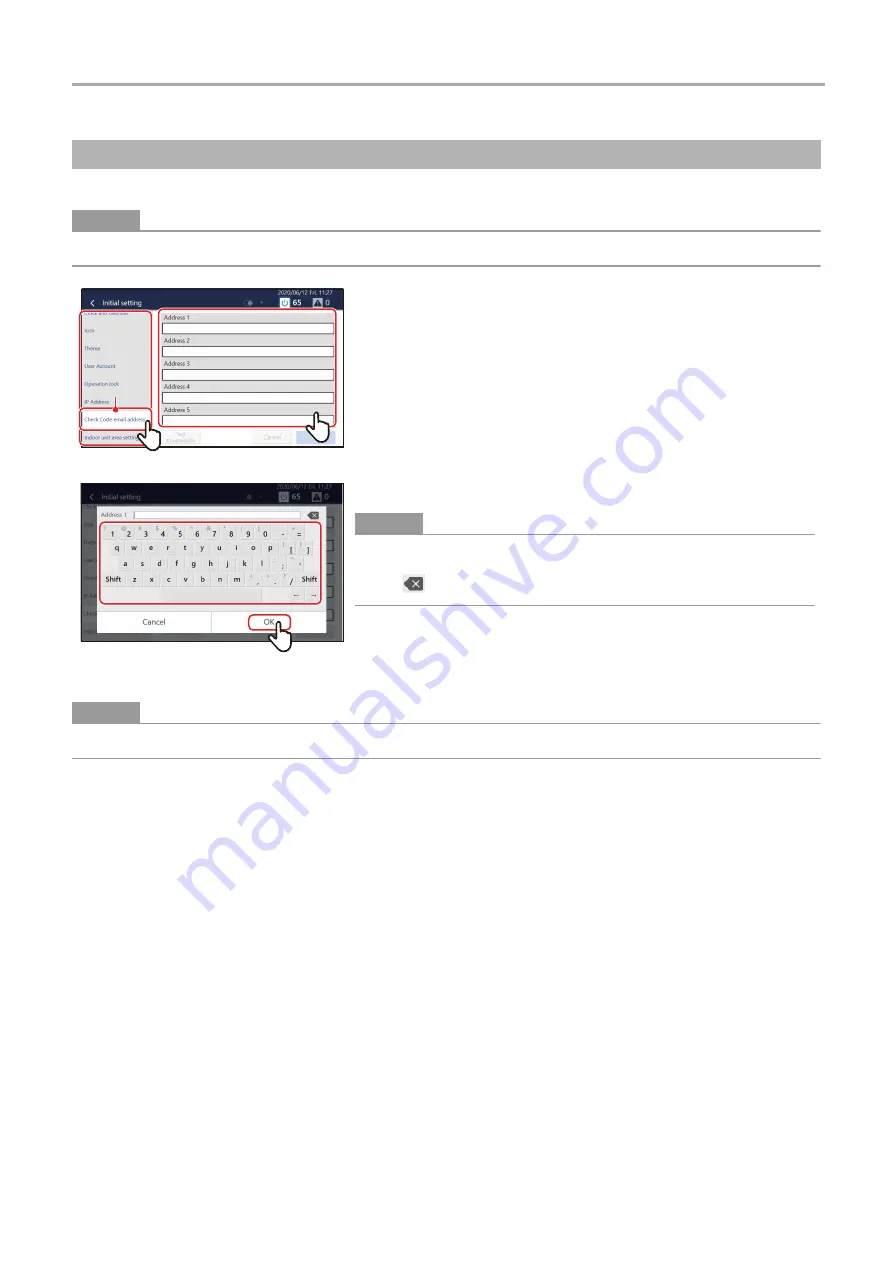
You can set the email address to send email to when an error occurs.


NOTE

Up to five email addresses can be set.


NOTE

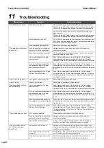
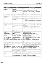
To test-send to the registered email address, tap [Test transmission], which displays after you tap [OK].

Set check code email destination

1

Tap [

1

-(2)

] with [

1

-(1)

] (P.81)

2

Tap the address field to register

3

Enter the email address on the keyboard, then tap [

3

-(1)

]


NOTE

• Tap [Shift] to toggle between upper case letters and lower case letters, and 

numbers and symbols.

• Tap 

 to delete one character.

4

Tap [OK]

1

-(1)

1

-(1)

1

-(2)

1

-(2)

3

-(1)

3

-(1)

Summary of Contents for BMS-CT1280TU

Page 1: ...use this product safely and correctly please read this owner s manual carefully before use and make sure that you fully understand the contents In particular please be sure to read the Safety Precautions After reading this manual be sure to keep it in a place where the operator of the Unit can always view it Touch Screen Controller For commercial use ...

Page 2: ...creen 17 Screen description 18 Layout screen 20 How to display the screen 20 Screen description 21 Group control screen CONTROL tab 22 How to display the screen 22 Screen description 23 Individual control screen CONTROL tab 24 How to display the screen 24 Screen description 25 For the Air to Water Heat Pump ATW 27 5 Perform Initial Settings 29 Unit Settings 29 Settings for Remote Monitoring with a...

Page 3: ... 50 Set Operation Details 52 Options for air conditioners 53 Options for Air to Water Heat Pump ATW 54 Turn ON OFF the ventilation function 55 Set ventilation mode 55 Setting the ventilation fan speed 55 Check the output status of the air conditioner s 55 Check the outdoor temperature detected by the outdoor unit 56 Make the night operation setting for the outdoor unit 56 Filter sign Reset 56 Set ...

Page 4: ...een Controller 75 Functions Menu Settings 76 How to display the Functions menu 76 Release demand control of outdoor unit 76 Set demand control schedule of outdoor unit 77 Add change power peak cut schedule 77 Delete an power peak cut schedule 79 Restrict operation mode 79 Set the operating schedule or the power peak cut schedule 79 Output data to a USB memory stick 80 Restart the unit 80 Exit the ...

Page 5: ...6 Exit Remote Control Software 97 10 Power Distribution 98 Power Distribution System Using the Energy Report Software 2 PC Software 98 How to use the power distribution system 99 11 Troubleshooting 100 12 Useful Information 103 13 Appendix 104 Specifications 104 Detailed specifications 104 Function list 105 List by Lock Level Level 106 14 Warranty and After Sales Service 108 About the Warranty 108...

Page 6: ...nge Set the temperature change range P 59 Save Mode Control air conditioner power P 57 Schedule settings Set the Operation Schedule P 43 Power peak cut schedule Set demand control schedule of outdoor unit P 77 To operate the Total Heat Exchange Unit Turn ON OFF the ventilation function P 55 To cancel the FILTER Sign after filter cleaning Filter sign Reset P 56 To connect to a PC that has Energy Re...

Page 7: ...atient treatment 3 Damage to property refers to extended damage related to houses household goods livestock or pets etc WARNING Request installation Ask the dealer from whom you purchased the unit or a professional for installation work Installation requires specialised technical expertise If you attempt to perform installation work yourself and perform the work incorrectly it may cause fire elect...

Page 8: ...umulating around the product may cause a fire Check the installation location Do not use this device in locations where children may be present Prohibited Do not drop the product or apply strong shock Doing so may cause a failure If anything is abnormal turn off the power If this product malfunctions turn off the original power supply and then contact the dealer from whom you purchased the product...

Page 9: ... Panel Operation Method Tap Touch your finger lightly on the screen and release it immediately Drag Tap an object on the screen hold your finger down and move Swipe Touch your finger lightly on the screen and move it in the desired direction Flick Touch the screen with your finger and move your finger quickly up down to left or the right ...

Page 10: ... conditioner s and ON OFF unit individually The individual control screen consists of three tabs CONTROL SCHEDULE and GRAPH P 24 Batch ON OFF screen You can check the operation status of the whole air conditioning system numerically You can also start stop the operation of the whole air conditioning system and configure the detailed settings P 49 Check code screen You can confirm check codes that ...

Page 11: ... units that can be controlled is 256 for air conditioners and 60 for ON OFF units The maximum number of air conditioners may change depending on the model combination Air Conditioning System Configurations Group 129 System Controller 256 groups up to a total of 256 units All Set all air conditioners at once Group All air conditioners and ON OFF unit are divided into 1 to 256 groups and settings ar...

Page 12: ...oom Air Conditioner home RAC This is a household air conditioner It can be connected to a unit via specialized equipment It is described as RAC in some parts of the manual ON OFF unit Indicates devices that cannot control or monitor the set temperature or operation mode among the managed devices Main equipment includes air to air heat exchangers ventilation fans etc Leak detector LD Refrigerant le...

Page 13: ...l etc Total of 256 units Light Commercial Package air conditioners for facilities Hot Water Module For use outside Japan only DX Coil Interface TA type TF type For use outside Japan only Air to Water Heat Pump ATW For use outside Japan only Room Air Conditioner home RAC TU2C LINK I F connection For use outside Japan only ON OFF unit Room Air Conditioner home ON OFF control interface connection For...

Page 14: ...splay colours differ The screens shown in the manual use the English display setting and the Type A theme setting For details of the display settings refer to Set the screen display P 82 and for details of the theme settings refer to Set the screen theme P 83 Screen description Switches for all air conditioners and ON OFF unit are displayed for each group You can change the group displayed by scro...

Page 15: ...y section Displays the current date and time Also the following will be displayed depending on the status and settings of the air conditioning system 6 Group name display section Displays the name of the group that displays the switch the name of the group to which the displayed switch belongs Tap the underlined name in the group name to display the drop down menu You can jump to other groups 7 FO...

Page 16: ...ned on or off This is the switch for the Air to Water Heat Pump ATW of just the hot water supply function This switch cannot be operated Displays the operating condition of the air conditioner Operation of the air conditioner s is locked P 75 Shows the operating status of the Air to Water Heat Pump ATW Operation of the Air to Water Heat Pump ATW is locked P 75 A malfunction in progress Tap to swit...

Page 17: ...Touch Screen Controller Owner s Manual 17 EN How to display the screen List screen 1 From the home screen tap A pulldown menu appears 2 Tap 2 1 The list screen appears 2 1 2 1 ...

Page 18: ...s of each unit on a display item by display item basis For an item without a function a is displayed 6 Check box for collective setting Enables you to select a unit subject to collective setting Each time you tap it the unit is selected deselected 7 Multiselection mode Displayed if you select the check box for collective setting so that you can set multiple units If you tap another check box for c...

Page 19: ...er Level Energy saving ratio Saving operation Soft Cooling Return Back Outdoor temp Night operation Power peak cut Forced Thermo OFF PURE Ventilation ON OFF Mode Fan Speed 24 hour ventilation Nighttime heat purge Control of Temperature Range Setting Auto Heat Cool Dry DHW ON OFF Auto mode Frost protection Anti bacteria Night set back Hot water boost HiPower ECO Power Select Fireplace Night operati...

Page 20: ...he layout screen is registered For details on how to configure the layout screen refer to the Operating Instructions of the Section Configuration Software How to display the screen Layout screen 1 From the home screen tap A pulldown menu appears 2 Tap 2 1 The layout screen appears 2 1 2 1 ...

Page 21: ...or layout and can be displayed as connected by wires to If you want to display the wires refer to the manual for the Section Configuration Software 6 Selected unit Displays the operating status of the tapped unit 7 Group display button Tap to display the operating status of the group 8 Group display Displays the operating status of units group by group 5 5 4 4 1 2 3 6 8 7 7 General layout screen D...

Page 22: ...er Owner s Manual 22 EN How to display the screen Group control screen CONTROL tab 1 Scroll the home screen to display the group you want to change the settings for then tap The CONTROL tab of the group screen is displayed ...

Page 23: ...in the group You can flick the group screen to display it 5 Display position Only the number of air conditioners or ON OFF unit registered in the group is displayed For the currently displayed screen is displayed 6 Switch tab Tap to switch to the 6 1 6 2 or 6 3 tab of the group screen 7 Run The ON OFF meter on the left side can be used to check the total number of units operated in the group On th...

Page 24: ...to display the screen Individual control screen CONTROL tab 1 Scroll the home screen display the air conditioner or ON OFF unit that you want to change the settings for then tap the switch The CONTROL tab of the individual control screen is displayed ...

Page 25: ...P 50 If it is not restricted is displayed If there are restricted items is displayed 4 option You can set or confirm the details of the operation method P 52 5 Display position Only the number of devices registered in the group is displayed For the currently displayed screen is displayed 6 SWITCH tab Tap to switch to the 6 1 6 2 or 6 3 tab of the individual control screen 7 Setting area You can ch...

Page 26: ...onnected leak detector LD is approaching If this icon is displayed contact your retailer or a service person FS unit Out of battery This icon is displayed when the battery in the FS unit dies If this icon is displayed contact your retailer or a service person FS unit Blocking This icon is displayed when the refrigerant in the FS unit is blocked Stirring operation This icon is displayed when the st...

Page 27: ...e between heating and cooling 3 ZONE1 Set temp You can change the set temperature of ZONE1 4 ZONE2 Set temp You can change the set temperature of ZONE2 5 DHW ON OFF icon Tap to turn the hot water on or off 6 Hot water setting temperature You can change the set temperature of hot water 7 Lock setting of remote control You can restrict the operating range of the local remote controller of the air co...

Page 28: ...nit only configurable items are displayed Icons are displayed only when they are registered P 83 If a malfunction occurs an check code is displayed Operation other than operation ON OFF is not possible Operation is impossible due to power outage hibernation state ...

Page 29: ...creation software is installed to create a local settings file 4 Upload the local settings file Connect the Unit to the PC via LAN and upload the local settings file While uploading the Unit restarts 5 Confirm the setting contents Check that the screen display of the Unit is set according to the local settings file perform ON OFF and confirm that the Unit operated on the screen matches the Unit th...

Page 30: ...ss P 87 3 Set a destination to send email to when a malfunction occurs P 88 Settings Operating enviroment The following environment is necessary to use this function Settings for Remote Monitoring with a PC System diagram Unit settings PC settings IP address Subnet mask Set it to be the same network as the Unit Example the Unit 192 168 2 80 PC 192 168 2 90 subnet 255 255 255 0 Drive C Ensure that ...

Page 31: ...Pv4 and click the Properties button 3 Select Use the following IP address set IP address to 192 168 2 and Subnet mask to 255 255 255 0 and click the OK button For enter an address different from that of the System Controller to connect NOTE If your PC is set to use a proxy server exclude the IP address of the System Controller How to set the IP address of the PC ...

Page 32: ...nu Server name or IP address Input the IP address that was set in Set the IP address of the Touch Screen Controller P 87 Language code Enter the following value according to the language Language Language Code Language Language Code Language Language Code Japanese JA Russian RU Estonian ET English EN Turkish TR Latvian LV French FR Swedish SV Croatian HR German DE Finnish FI Slovak SK Italian IT D...

Page 33: ...report for electric power distribution with a PC When using the Energy Report Software 2 apply the following settings NOTE For details on how to use the Energy Report Software 2 refer to the Operating Instructions of the Energy Report Software 2 1 Set the IP address of the Unit P 87 1 Install the Energy Report Software 2 on the PC 2 Register the target system this Unit in the Energy Report Softwar...

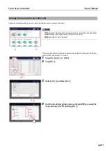
Page 34: ...hod 1 Tap 2 Tap 2 1 or 2 2 3 Select the equipment to add to be operated and then tap 3 4 All the air conditioners and the selected equipment start or stop operations The selected equipment and air conditioners are added to equipment to be operated 2 1 2 1 2 2 2 2 3 1 3 1 3 2 3 2 3 3 3 3 3 4 3 4 No Item Equipment to be added 3 1 Including external devices External device 3 2 Including ESTIA AC Air ...

Page 35: ... 3 2 General purpose device control I F External device DI DO Air to Air Heat Exchanger External device Equipment in 3 1 Air conditioning and hot water supply Air conditioning only Equipment in 3 3 Air conditioning and hot water supply Water temperature only RAC Control units All Air to Water Heat Pump ATW Air to Water Heat Pump ATW ...

Page 36: ...1 2 2 2 2 3 1 3 1 3 2 3 2 3 3 3 3 3 4 3 4 No Item Equipment to be added 3 1 Including external devices External device 3 2 Including ESTIA AC Air to Water Heat Pump ATW with air conditioning function 3 3 Including ESTIA DHW Air to Water Heat Pump ATW in hot water supply function Touch screen Controller Air conditioner Equipment in 3 2 General purpose device control I F External device DI DO Air to...

Page 37: ...onditioner or ON OFF unit that you want to change the settings for 2 Drag or flick the of the corresponding switch Drag or flick to the right to start operation Drag or flick to the left to stop operation NOTE You can also start stop operation by tapping the power icon on the CONTROL tab on the individual control screen displayed by tapping the switch ...

Page 38: ...screen is displayed 3 2 Set the check box of 3 2 to You can now change the settings 3 3 Select 3 3 or 3 4 and tap 3 5 Return to the batch settings screen 3 4 Change the other items with reference to steps 3 1 to 3 3 For the setting details see the following table No Name Functions 1 ON OFF Can be set to ON OFF 2 Mode Can be set to Auto Heat Dry Cool Fan NOTE A bar is displayed at the bottom of the...

Page 39: ...he following NOTE Depending on the connected model it may not be configurable 5 Set temp Tap to change the set temperature NOTE When set to a temperature outside the setting range limit of each operation mode the temperature is changed to the upper or lower limit of the setting range If there are Dual Set Point compatible models in the group two tabs will be displayed When you tap 3 6 one set temp...

Page 40: ...Including external devices External device 5 2 Including ESTIA AC Air to Water Heat Pump ATW with air conditioning function 5 3 Including ESTIA DHW Air to Water Heat Pump ATW in hot water supply function Touch screen Controller Air conditioner Equipment in 5 2 General purpose device control I F External device DI DO Air to Air Heat Exchanger External device Equipment in 5 1 Air conditioning and ho...

Page 41: ...ons 1 Mode Can be set to Auto Heat Dry Cool Fan NOTE A bar is displayed at the bottom of the icon for the currently selected mode Operation modes that cannot be set are not displayed 2 Wind direction Tap to switch to the following NOTE Depending on the connected model it may not be configurable 3 1 2 4 4 1 4 1 Operation Mode Setting Range Auto Cool Cool Dry Swing ON Swing OFF F1 F2 F3 Swing ON Ret...

Page 42: ... unit after partial compensation Depending on conditions such as the installation site of the indoor unit it may differ from actual room temperature In this area icons and text are displayed such as for frost protection preparing for operation or preparing for heating operation Example of a model without a flap Example of a case in which the wind direction cannot be changed Since you cannot set th...

Page 43: ...es and the Weekly schedule is disabled for that day This section explains how to view the SCHEDULE tab when setting the operation schedule NOTE Refer to the description of the CONTROL tab for the display items that are not explained P 22 24 Group screen The schedule set for the air conditioners or ON OFF unit in the group is displayed in list format in time units Set the Operation Schedule Screen ...

Page 44: ...he setting screen of Weekly schedule 4 is displayed at the times when the schedule is set When operation start stop is set ON or OFF is displayed below When setting change is set is displayed below Also the currently displayed schedule is displayed in blue 5 The schedule settings content ON OFF Mode Temp Lock more is displayed 6 You can switch the display to the previous or next schedule 7 The tim...

Page 45: ... Schedule settings can be applied from either the group screen or the individual control screen In the following procedure the individual control screen is used to explain Create a new weekly schedule 1 Tap 1 1 on the group screen or individual control screen 2 Tap 2 1 3 Tap 4 Tap or flick to set the start time and tap 4 1 1 1 1 1 2 1 2 1 4 1 4 1 ...

Page 46: ...ete the operation schedule P 70 5 Select the day of the week to execute and tap 5 1 6 Select the air conditioner s or ON OFF unit for setting the schedule and tap 6 1 You cannot select a model that has already been scheduled at the same time 7 Tap the check box of 7 1 and set it to then select 7 2 or 7 3 and tap 7 4 You can only set ON OFF here A schedule has been registered 5 1 5 1 6 1 6 1 7 1 7 ...

Page 47: ...e individual control screen The following procedure is explained using the individual control screen Create a new special day schedule 1 Tap 1 1 on the group screen or the individual control screen 2 Tap 2 1 3 Tap 4 Tap and set the schedule name A keyboard is displayed Enter the name and then tap 4 1 5 Tap to go to step 6 NOTE Tap Shift to toggle between upper case letters and lower case letters a...

Page 48: ...details of the special day schedule P 65 When deleting a registered schedule refer to Delete the operation schedule P 70 6 Tap or flick to set the start date and then tap 6 1 7 Tap the check box of 7 1 and set it to then select 7 2 or 7 3 and tap 7 4 You can only set ON OFF here The schedule is registered 6 1 6 1 7 1 7 1 7 2 7 2 7 3 7 3 7 4 7 4 ...

Page 49: ...F unit it is displayed in 2 1 3 You can change the operation status of the overall air conditioning system P 34 For the Option settings see step 3 on P 38 4 Tap to close the batch ON OFF screen NOTE You can also tap to close 5 The check code check content notice code notice content occurrence location and occurrence time are displayed 6 Stop operation of all air conditioners and ON OFF unit where ...

Page 50: ...ch settings screen P 38 In the following procedure the CONTROL tab of the individual control screen is used to explain Local Remote Controller Lock 2 Tap 2 1 NOTE appears if it is not locked appears if there is a locked item 3 Tap the check box of the function whose setting you want to change to set it to NOTE The display items vary depending on the model 4 Select 4 1 or 4 2 then tap 4 3 REQUIREME...

Page 51: ...ill be cancelled when the power returns Ask service personnel if you want to continue the local remote control prohibited status after returning from a power failure NOTE If you perform an operation that is locked with the local remote controller the lock screen or a message will be displayed Lock screen example Energy saving neo remote controller Wired remote controller ...

Page 52: ...ging in group units display the batch settings screen P 38 In the following procedure the individual control screen is used to explain 3 Scroll up and down to display the items you want to set check Set Operation Details 2 Tap 2 1 The option screen appears No Functions 1 The function name appears 2 The currently set contents are displayed If the settings are invalid is displayed 3 When the setting...

Page 53: ...t operation 1 Night operation 2 P 56 Filter sign reset You can clear the FILTER Sign You can clear the Hour OK Cancel P 56 Inspection You can check the check code that has occurred Soft Cooling You can set to Middle COOL ON OFF P 56 Energy saving ratio You can control the cooling heating output of the air conditioner s Release 100 Max 50 100 50 0 P 57 Saving operation You can operate the indoor un...

Page 54: ... to low sound ON OFF P 56 Hot water boost Hot water boost can be controlled ON OFF P 61 Anti bacteria Antibacterial can be allowed Enable Disable P 62 Frost protection Frost protection can be controlled ON OFF P 58 ESTIA information Shows the following operating statuses Boiler operation Comp operation DHW heater Heater Pump 1 operation Pump 2 operation P 62 Check Code During backup operation Disp...

Page 55: ...on fan speed of the ventilator connected to the air to air heat exchange unit or the air conditioner The choices displayed depend on the model NOTE Depending on the connected model it may not be configurable It is displayed when Ventilation ON OFF is ON and setting change is possible Details for unbalance settings vary depending on the settings of the connected model Check the output status of the...

Page 56: ...model it may not be displayed When Night Operation is set turn on the Silent Mode setting of the Hydro Unit to operate the Air to Water Heat Pump Filter sign Reset When a device has operated for a certain period of time a warning Filter sign is displayed to indicate that the filter should be cleaned After filter cleaning tap 1 NOTE Depending on the connected model it may not be displayed If you se...

Page 57: ...heating power of the air conditioner such that the outdoor unit compressor is stopped When this state is reached the air conditioner becomes a fan and cold hot air is no longer output To release Thermo OFF display the settings screen and press OK NOTE Depending on the connected model it may not be displayed Configure and confirm the Return Back settings You can configure and check the Return Back ...

Page 58: ...hen heating is on FP is displayed in the place that the set temperature is displayed while frost protection is operating Frost protection is disabled by the following operations unless disabled from the frost protection settings Indoor unit is turned off Operation mode is changed to something other than heating Set temperature is changed NOTE May not be displayed depending on the model connected O...

Page 59: ...ap the upper lower limit temperature you want to change NOTE Depending on the connected model it may not be configurable 2 Tap the number enter the temperature and tap 2 1 HiPower This function monitors and controls HiPower operation of targeted equipment While being controlled is displayed to the right of the unit name NOTE May not be displayed depending on the model connected ECO This function m...

Page 60: ...ed to the right of the unit name NOTE May not be displayed depending on the model connected Fireplace This function monitors and controls Fireplace operation of targeted equipment While being controlled is displayed to the right of the unit name NOTE May not be displayed depending on the model connected Notice Code Displays Notice Codes that occur during operations NOTE May not be displayed depend...

Page 61: ...ot be displayed depending on the model connected Night set back This function monitors and controls Night set back While being controlled is displayed to the right of the unit name NOTE May not be displayed depending on the model connected Hot water boost This function monitors and controls Hot water boost While being controlled is displayed to the right of the unit name The actual operation depen...

Page 62: ...peration depends on the time at the local remote control For details refer to the owner s manual for the local remote control NOTE May not be displayed depending on the model connected ESTIA information Shows the following operating statuses Boiler operation Comp operation DHW heater Heater Pump 1 operation Pump 2 operation NOTE May not be displayed depending on the model connected ...

Page 63: ... using the individual control screen NOTE If a day is set in both the Weekly schedule and the Special day schedule the Special day schedule applies and the Weekly schedule is disabled for that day Change the Operating Schedule Change the details of the weekly schedule 1 Tap 1 1 on the group screen or the individual control screen 2 Tap 2 1 3 Tap 3 1 of the schedule you want to modify 4 Modify the ...

Page 64: ...h Screen Controller Owner s Manual 64 EN 5 Scroll the screen and tap the value of the item you want to set After changing the setting tap OK See Setting items list P 67 for the items that can be configured ...

Page 65: ...Tap 2 1 3 Tap 3 1 of the schedule you want to modify 3 1 Unit setting Go to step 4 3 2 Special day setting Go to step 5 3 3 Operating schedule setting Go to step 6 4 Modify the target air conditioner s or ON OFF unit then tap 4 1 5 Tap the date you want to configure modify the settings and then tap 5 1 1 1 1 1 2 1 2 1 3 2 3 2 3 1 3 1 3 3 3 3 4 1 4 1 5 1 5 1 ...

Page 66: ...r s Manual 66 EN 6 Tap 6 1 of the time you want to modify 7 Scroll the screen and tap the value of the item you want to set After changing the setting tap OK See Setting items list P 67 for the items that can be configured 6 1 6 1 ...

Page 67: ... OFF by this setting Operation mode setting Mode To enable the setting set the check box of 2 to and select a value Set temperature setting Set temp To enable the setting set the check box of 3 to tap then change the set temperature Return Back settings Return Back An energy saving function whereby if you temporarily change the set temperature to one which increases the load you can automatically ...

Page 68: ...f 3 to For details see Control air conditioner power P 57 Ventilation operation setting Ventilation ON OFF You can turn ON OFF the operation of the ventilator connected to the air to air heat exchanger s or air conditioner s To enable the setting set the check box of 4 to and apply the setting Vent Mode Ventilation Mode You can set the ventilation mode of the ventilator connected to the air to air...

Page 69: ...eck box and then tap to change the set temperature The set temperature cannot be changed in increments of 0 5 C ZONE2 Set temp Set temp ESTIA ZONE2 This setting item is specifically for the Air to Water Heat Pump ATW in the air conditioning function To enable this setting select for the Enable check box and then tap to change the set temperature The set temperature cannot be changed in increments ...

Page 70: ... 1 1 on the group screen or individual control screen 2 Tap 2 1 to go to step 4 3 In case of Special day setting tap 3 1 Tap 3 2 of the schedule you want to modify to go to step 4 4 Tap Some displayed items differ between the Weekly schedule screen and the Special day schedule screen but the procedure shown below is the same 5 Set the check box of the schedule you want to delete to then tap 5 1 1 ...

Page 71: ...ars Group screen Individual control screen No Functions 1 The hourly or daily operation hours are shown as a bar graph For the individual control screen the outdoor temperature room temperature and set temperature are displayed as a line graph The set temperature line graph is not displayed for the Air to Water Heat Pump ATW 2 The operation hours for the displayed summary period is displayed 3 Dis...

Page 72: ... display language The owner s manual is displayed No Name Icon Functions 1 Bookmark You can switch bookmarks between display and non display 2 Previous page Displays the previous page 3 Next page Displays the next page 4 Enlarge reduce Used to enlarge and reduce the display 5 Language selection Select the display language 6 Bookmark list Displays the title of each chapter Tap a title to display th...

Page 73: ...codes are displayed You can display notices that have occurred in a list including currently occurring ones For details confirm with the dealer Confirm Check Code History 1 Tap 1 1 appears 2 Tap 2 1 The detected check codes are listed in chronological order Confirm Notice Code History 2 1 2 1 1 1 1 1 Past check codes are displayed with a white background Currently occurring check codes are display...

Page 74: ...4 1 An electric power graph is displayed 2 1 2 1 1 1 1 1 3 1 3 1 3 2 3 2 3 3 3 3 3 4 3 4 3 1 All systems Daily You can display the total electric power on a daily basis on a graph 3 2 All systems Monthly You can display the total electric power on a monthly basis on a graph 3 3 Select System Daily You can select the watt hour meter to sum and display the daily electric power on a graph 3 4 Select ...

Page 75: ... the Unit will be locked automatically after 5 minutes have passed after an operation has completed When the lock is set if you tap a function that cannot be operated the message operation function is locked is displayed Also appears in the menu Restrict Operation of the Touch Screen Controller 1 Tap 1 1 appears 2 Tap 2 1 Below the screen for release is explained 3 Tap 3 1 To change the auto lock ...

Page 76: ... Release power peak cut P 76 Power peak cut schedule P 77 Operation mode restriction P 79 Scheduler Operation P 79 Output to USB memory P 80 System reboot P 80 Shut down P 80 Release demand control of outdoor unit 1 Tap 1 2 with 1 1 2 Tap 2 1 Outdoor demand set for all outdoor units is released NOTE Outdoor demand can be set by the Power peak cut schedule P 77 Outdoor demand may function with digi...

Page 77: ... 9 00 to 18 00 90 for 18 00 to 21 00 and 100 No power peak cut for 21 00 to 9 00 on next day 1 Tap 1 2 with 1 1 P 76 2 Tap to register new To change tap of the schedule you want to change NOTE When the demand function is functioning at the current time appears 3 Tap 3 1 and set the check box of the outdoor unit for setting the Power peak cut schedule to NOTE The schedule number will be displayed o...

Page 78: ... released in the following cases When 100 No power peak cut is set in the schedule When demand control of the outdoor unit has been released P 76 Demand control continues even across days Example When the demand rate is set to 0 on Monday at 21 00 and release is set at 9 00 on Tuesday The demand rate is set to 0 from Monday at 21 00 to Tuesday at 9 00 and demand release occurs at 9 00 on Tuesday 5...

Page 79: ... selected When a restricted operation mode is selected the Thermo OFF state is set You can disable registered Operation Schedules and Power peak cut schedules so that they do not operate 1 Tap Scheduler Operation in the Functions menu P 76 2 Set the check box to if you do not want to operate each schedule or set the check box to to operate them then tap OK 1 Tap 1 2 with 1 1 P 76 2 Tap 3 Set the c...

Page 80: ...mory stick is not connected OK will not be enabled You can restart the Unit The schedule is not executed during restart 1 Tap System reboot in the Functions menu P 76 2 Tap OK Terminate the operation of the Unit NOTE This function turns off the power to the System Controller It does not stop the air conditioners connected to the Unit Output data to a USB memory stick Restart the unit Exit the syst...

Page 81: ... tap 2 1 3 1 appears 3 Tap the item you want to set with 3 1 The settings screen of the selected item appears on the right For details on the setting contents of each item refer to the following Display P 82 Clock and calendar P 82 Icon P 83 Theme P 83 User Account P 84 Operation lock P 86 IP Address P 87 Check code email address P 88 Indoor unit area setting P 89 Indoor unit name setting P 91 Are...

Page 82: ...hour forward and when set to 2 it moves one hour back While daylight saving time is set appears in the upper right corner of the screen 3 1 3 1 1 1 1 1 1 2 1 2 2 2 4 4 3 3 2 2 1 1 6 6 5 5 1 Language You can change the display language of the screen 2 Date format You can change the format of the date displayed in the upper right of the screen 3 First day of the week You can change the first day of ...

Page 83: ...s 1 Tap 1 2 with 1 1 P 81 2 Tap the device you want to set with 2 1 3 Tap the icon you want to set in the icon list The selected icon is displayed in 2 1 4 Tap 4 1 Ventilation fan Circulator Room air conditioner Curtain Alarm Humidifier Dehumidifier Lighting Cubicle Water storage tank General switch Security Pump Camera Set the screen theme 1 Tap 1 2 with 1 1 P 81 2 Tap the drop down menu and sele...

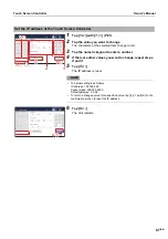
Page 84: ...in the list NOTE The following users are registered in advance You can also change delete users Name TCC Password TCC Level Administrators 3 Tap 3 1 or 3 2 In the following procedure the screen in the case of addition is used to explain 4 Set Name only when adding and password Tap the entry field to display the keyboard After entering the characters tap 4 1 NOTE Tap Shift to toggle between upper c...

Page 85: ...functions can be used Power Users The following functions cannot be used Confirm change the operation schedule Menu Functions Menu Initial setting Guests Only the operation status can be confirmed The settings cannot be changed 7 Tap 7 1 1 Tap 1 2 with 1 1 P 81 2 Tap the row you want to delete 3 Tap 3 1 It will be deleted from the list 4 Tap 4 1 Deletion is confirmed 7 1 7 1 2 1 2 1 2 1 1 1 1 3 1 ...

Page 86: ...default setting password is 1048 3 Select the protection level during lock NOTE You can change the password that sets the operation lock Tap 3 1 to display the change password input screen Enter the changed password tap OK re enter it on the re entry screen then tap OK 4 digit passwords can be set 4 Tap 4 1 1 2 1 2 1 1 1 1 2 1 2 1 3 4 1 4 1 3 1 3 1 ...

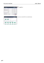
Page 87: ...c keypad to enter a number 4 If there are other values you want to change repeat steps 2 and 3 5 Tap 5 1 The IP address is reset NOTE The initial setting is as follows IP address 192 168 2 80 Subnet mask 255 255 255 0 Default gateway 0 0 0 0 To return a changed value to the specified value tap 1 Tap OK on the confirmation screen to reset the IP address 6 Tap 6 1 The Unit restarts 2 1 2 1 2 1 1 1 1...

Page 88: ...gistered email address tap Test transmission which displays after you tap OK Set check code email destination 1 Tap 1 2 with 1 1 P 81 2 Tap the address field to register 3 Enter the email address on the keyboard then tap 3 1 NOTE Tap Shift to toggle between upper case letters and lower case letters and numbers and symbols Tap to delete one character 4 Tap OK 1 1 1 1 1 2 1 2 3 1 3 1 ...

Page 89: ...area 2 are allocated automatically in the upper section of the home screen 2 Each indoor unit in the area The procedure below is used as an example to explain how to move the indoor unit unit 001 set in area 1 to area 2 1 Tap 1 2 in 1 1 P 81 2 Tap 2 1 3 Select 3 1 and tap 3 2 4 Set the check box of the indoor unit unit 001 you want to move to area 2 to and tap 4 1 1 2 1 2 1 2 2 1 2 1 1 1 1 1 3 1 3...

Page 90: ...Touch Screen Controller Owner s Manual 90 EN 5 Tap 5 1 The indoor unit unit 001 is moved to area 2 5 1 5 1 ...

Page 91: ...se letters and lower case letters and numbers and symbols Tap to delete one character 3 Tap 3 1 Set the area name 1 Tap 1 2 in 1 1 P 81 2 Tap the name you want to change in the list A keyboard is displayed Enter the name and then tap 2 1 NOTE Tap Shift to toggle between upper case letters and lower case letters and numbers and symbols Tap to delete one character 3 Tap 3 1 1 2 1 2 1 1 1 1 2 3 1 3 1...

Page 92: ...settings Energy threshold Controls operation based on the pulse signal from the pulse transmission type watt hour meter Peak cut signal reception Controls operation based on the signal from the external demand device NOTE Before setting these items initial settings are required For details contact service personnel System diagram Set the screen brightness 1 Tap 1 2 with 1 1 P 81 2 Select the brigh...

Page 93: ...e is displayed Before setting these items initial settings are required For details contact service personnel 4 Set data in 4 1 and 4 2 NOTE In Measurement time set the measurement time for power usage For Threshold 1 to Threshold 4 set the power usage in the measurement time cycle A threshold of 0 means that no threshold is set Enter thresholds starting with Threshold 1 in such a way that the thr...

Page 94: ...peak cut control to execute if the threshold is exceeded NOTE You can set power peak cut controls with seven stages from 100 no restriction to 0 operation stop You can set them for each of the outdoor units connected to the Unit Before setting thresholds for outdoor units initial settings are required For details contact service personnel 7 Tap 7 1 and tap OK NOTE Tap 7 2 to check the setting cont...

Page 95: ...ect the capacity limit to use when the power peak cut signal is entered NOTE You can set them with seven stages from 100 no restriction to 0 operation stop You can set them for each of the outdoor units connected to the Unit Before setting power peak cut controls initial settings are required For details contact service personnel 4 Tap 4 1 and tap 4 2 A popup screen appears Confirm the information...

Page 96: ...with a PC P 30 NOTE Some functions cannot be used from a PC For details please see List by Lock Level Level P 106 NOTE Up to 16 users can log in at the same time Log in to Remote Control Software 1 Double click AMTC_UI_ on the desktop 2 Enter 2 1 2 2 then click 2 3 User ID password Use the user account set up in step 1 of Unit settings P 30 The Remote Control Software home screen is displayed Log ...

Page 97: ...ller Owner s Manual 97 EN 2 Click 2 1 3 Click 3 1 You are logged out from the Remote Control Software Exit Remote Control Software 1 Tap 2 Tap 2 1 3 Tap 3 1 Exit the Remote Control Software 2 1 2 1 3 1 3 1 2 1 2 1 3 1 3 1 ...

Page 98: ...mmarize the operation results in a report format and calculate the billing amount Example report CAUTION This system calculates the distribution of the power by load ratio estimated for each air conditioner The result may differ from the actual power consumed In addition the result is not calculated based on the Measurement Act and cannot be used officially This system correctly calculates and dis...

Page 99: ...o the USB memory stick using the Unit s Output to USB memory and import the data using the Energy Report Software 2 2 Create monthly reports and daily reports Create a monthly report or daily report from Change display Report in the Energy Report Software 2 3 From the Monthly report screen or the Daily report screen click the month or day you want to display 4 Click the Output button NOTE For deta...

Page 100: ... power From Menu turn off the power Select Menu Functions shut down I want to reboot Reboot from the menu Select Menu Functions System reboot The air conditioner settings change arbitrarily Are you operating with the local remote control Even if the air conditioner is run with this Unit if it is stopped afterwards with the local remote control it will stop The latter operation of this Unit or the ...

Page 101: ...ion is displayed under Menu Information The webpage of the Controller is not displayed Is the power to the System Controller on If the power to the System Controller is not on you cannot connect to the webpage Confirm if the power is on Is the LAN cable connected The webpage is not displayed unless the PC and the LAN of this Unit are connected Check the LAN cable connection and network settings Ha...

Page 102: ...gether with all centralized controllers including this Unit Ask service personnel to use them in combination I want to use multiple units in combination Number of units that can be used in combination in the same network It is possible to use up to 8 units together with all centralized controllers including this Unit Ask service personnel to use them in combination The LCD sometimes turns black fo...

Page 103: ...h even if you operate the Touch Screen Controller The function is not provided by the air conditioner There may be an error in the operation method Please check the operation explanation of the function This is because switching of HEAT and COOL in the operation mode is prohibited It is not set even when operating the Touch Screen Controller Problem Cause Solution The air conditioner does not oper...

Page 104: ...printing is required Specifications Detailed specifications Power supply 220 240 V AC 50 60 Hz Consumed current 1 17 A Operating temperature humidity range 0 C to 40 C 10 to 90 RH no dew condensation Dimensions mm H136 W205 D10 80 Embedded dimensions shown in parenthesis Mass 1 34 kg Touch Screen Controller 0 45 kg power adapter LCD Type 7 TFT liquid crystal 800 480 167 000 colours Touch Screen Pr...

Page 105: ...edule Setting unit Per unit Setting unit Weekly schedule per day of the week Setting unit Special day schedule per date Setting time 00 00 to 23 59 Setting content ON OFF Mode Set temp Local remote controller operation lock unlock Return Back Night operation Energy saving ratio Ventilation operation Vent Mode Maximum number of schedules per day 64 External input Inputs Main unit 8 inputs DIO inter...

Page 106: ...vel of the user account Full functional operation Partially restricted Cannot be used List by Lock Level Level Item Unit Operation Remote Operation Operation Lock None Operation Lock Level 1 Operation Lock Level2 Admini strators Power Users Guests Home screen List screen Layout screen Batch ON OFF screen Check Code screen Group screen CONTROL tab SCHEDULE tab GRAPH tab Individual control screen CO...

Page 107: ...er Operation Output to USB Memory System reboot Shut down Initial setting Display Clock and calendar Icon Theme User Account Operation Lock IP Address Check Code email address Indoor unit area setting Indoor unit name setting Area name setting Backlight Power peak cut User s manual Information screen Logout Item Unit Operation Remote Operation Operation Lock None Operation Lock Level 1 Operation L...

Page 108: ...blem immediately shut off the power supply and contact us Please inform us of the following when requesting a repair Customer name Address phone number Product model name and serial number Installation date Failure status as much detail as possible For after sales service please contact here About the Warranty About After Sales Service Contact for after sales service 1 Tap then tap 1 1 The contact...

Page 109: ...LFHQVH DJUHHPHQWV DQG FDQ EH XVHG IUHHO IRU DQ SXUSRVH WKH 18 OLFHQVH EHLQJ WKH PRVW UHVWULFWLYH VHH EHORZ IRU GHWDLOV RZHYHU QRQH RI WKDW WHUP LV UHOHYDQW DW WKLV SRLQW LQ WLPH OO RI WKHVH UHVWULFWLYHO OLFHQFHG VRIWZDUH FRPSRQHQWV ZKLFK KH WDONV DERXW KDYH EHHQ UHPRYHG IURP 2SHQ66 L H 56 LV QR ORQJHU LQFOXGHG IRXQG LQ WKH 2SHQ66 OLEUDU LV QR ORQJHU LQFOXGHG LWV XVH LV GHSUHFDWHG 6 LV QRZ H WHUQDO...

Page 110: ... 6 25 85 2 7 352 5 0 72 23 5 7 7 1 27 5 352 5 06 9 1 68 2 5 25 27 5 3 57 6 1 9 6 2 7 3266 7 2 68 0 6 VVK NH VFDQ ZDV FRQWULEXWHG E DYLG 0D LHUHV XQGHU D 6 VW OH OLFHQVH RS ULJKW E DYLG 0D LHUHV GP OFV PLW HGX 0RGLILFDWLRQ DQG UHGLVWULEXWLRQ LQ VRXUFH DQG ELQDU IRUPV LV SHUPLWWHG SURYLGHG WKDW GXH FUHGLW LV JLYHQ WR WKH DXWKRU DQG WKH 2SHQ 6 SURMHFW E OHDYLQJ WKLV FRS ULJKW QRWLFH LQWDFW 7KH 5LMQGD...

Page 111: ...HSURGXFH WKH DERYH FRS ULJKW QRWLFH WKLV OLVW RI FRQGLWLRQV DQG WKH IROORZLQJ GLVFODLPHU LQ WKH GRFXPHQWDWLRQ DQG RU RWKHU PDWHULDOV SURYLGHG ZLWK WKH GLVWULEXWLRQ 1HLWKHU WKH QDPH RI WKH 8QLYHUVLW QRU WKH QDPHV RI LWV FRQWULEXWRUV PD EH XVHG WR HQGRUVH RU SURPRWH SURGXFWV GHULYHG IURP WKLV VRIWZDUH ZLWKRXW VSHFLILF SULRU ZULWWHQ SHUPLVVLRQ 7 6 62 7 5 6 3529 7 5 176 1 2175 87256 CC 6 6 1 1 35 66 2...

Page 112: ...S ULJKW QRWLFH WKLV OLVW RI FRQGLWLRQV DQG WKH IROORZLQJ GLVFODLPHU LQ WKH GRFXPHQWDWLRQ DQG RU RWKHU PDWHULDOV SURYLGHG ZLWK WKH GLVWULEXWLRQ 7 6 62 7 5 6 3529 7 87 25 CC 6 6 1 1 35 66 25 03 55 17 6 1 8 1 87 127 0 7 72 7 03 55 17 6 2 0 5 17 7 1 71 66 25 3 57 8 5 385326 5 6 0 1 12 9 17 6 7 87 25 25 1 5 7 1 5 7 1 17 63 03 5 25 216 48 17 0 6 1 8 1 87 127 0 7 72 352 85 0 17 2 68 67 787 22 6 25 6 59 6...

Page 113: ...ent to fill this in at the time of purchase in case you need to request repair etc Model Name BMS CT2560U E BMS CT2560U TR Installation Date Year Month Day Name of dealer from whom you purchased the unit Phone number DEB5869001 3 ...

Reviews: