48
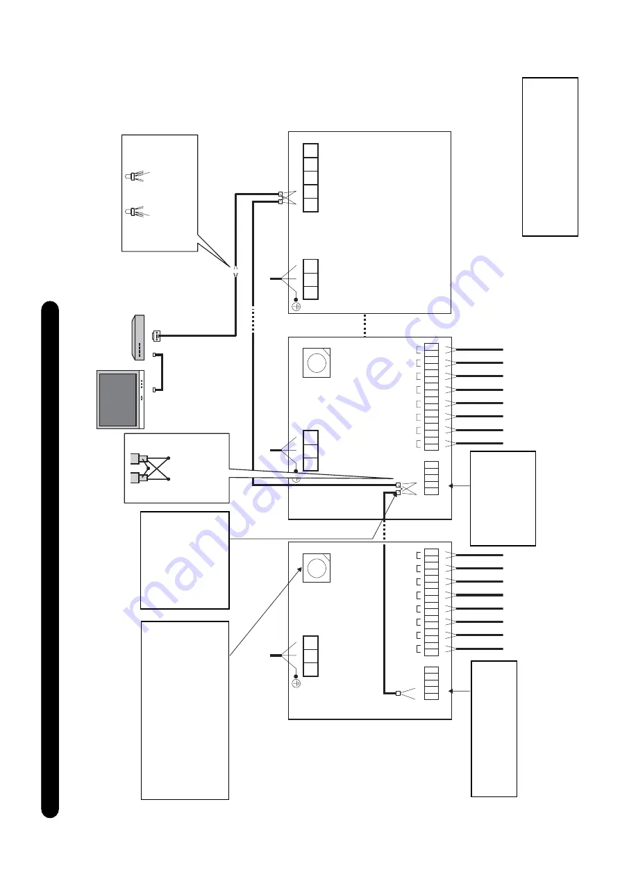
Connection dia
gram (ENERGY MONIT
ORING RELA
Y INTERF
A
CE (BMS-IFWH3E))
A
B
A
B
A
B
L
N
FG
U1
U2
TCC-LINK
RS-485
L
NL
N
DI 8
DI 7
DI 6
DI 5
DI 4
DI 3
DI 2
DI 1
DI 2
DI 1
DI 8
DI 7
DI 6
DI 5
DI 4
DI 3
1
SW1
SW1
ADDRESS
4
ADDRESS
A
B
RS-485
A
B
RS-485
Set the Energy Monitoring Relay
Interface address with SW1. Assign 1 to
4 to each address to avoid duplication.
Each interface has its own address and
can be set independently
.
CA
UTION
:
The SW1 setting is read
when the power is turned on. Push the
reset switch after changing the address.
Connect the
respective
shield wires of
two cables.
The shield earth of
the RS-485 signal
wires should be
single-point earth.
Earth the wires on
the Intelligent server
side. Do not earth
here.
CA
UTION
: RS-485
signals A and B
ha
v
e
polar
ity
. Be
careful when
connecting the RS-
485 wire.
CA
UTION
: No ter
minator resistor
setting switch is provided on the
Energy Monitoring Relay Interface.
Set the RS-485 terminator resistor
on the
TCS-NET Rela
y Interf
ace
.
TOUCH SCREEN CONTROLLER
(BMS-TP0640/5120)
INTELLIGENT SER
VER
(BMS-LSV2E)
Red/Orange
Bro
wn/Y
ello
w
P
o
w
er supply
Red
Orange
Y
ello
w
Brown
Crimp 3 wires with
a close end wire joint.
TCS-NET RELAY
INTERFACE
ENERGY
MONITORING
INTERFACE
ENERGY MONITORING
INTERFACE (BMS-IFWH3E)
CA
UTION
: RS-485 signals A
and B ha
v
e
polarity
. Be
careful when connecting the
RS-485 wire.
Power meter 1
Power meter 2
Power meter 3
Power meter 4
Power meter 5
Power meter 6
Power meter 7
Power meter 8
Power meter 1
Power meter 2
Power meter 3
Power meter 4
Power meter 5
Power meter 6
Power meter 7
Power meter 8
P
o
w
er supply
P
o
w
er supply
Summary of Contents for BMS-TP0640ACE
Page 1: ...FILE NO A04 016 TCS NET AIR CONDITIONING CONTROL SYSTEM TOUCHSCREENCONTROLLER TENTATIVE ...
Page 16: ...16 ...
Page 17: ...17 2 SYSTEM CONFIGURATION 2 1 Touch screen controller system configuration ...
Page 22: ...22 ...
Page 54: ...54 ...
Page 96: ...96 ...
Page 103: ...103 ...
Page 104: ......


