background image

Stratagy ES Model C1 Installation Guide

Step 3: Set Voice Board’s Hardware Switches

2

Stratagy ES Model C1 Installation Guide    12/01

Step 3: Set Voice Board’s Hardware Switches

Important!

Model C1 has only one ISA slot available for a voice board (maximum port capacity 
of up to four ports).

ProLine/2V or Dialog/4 Voice Board

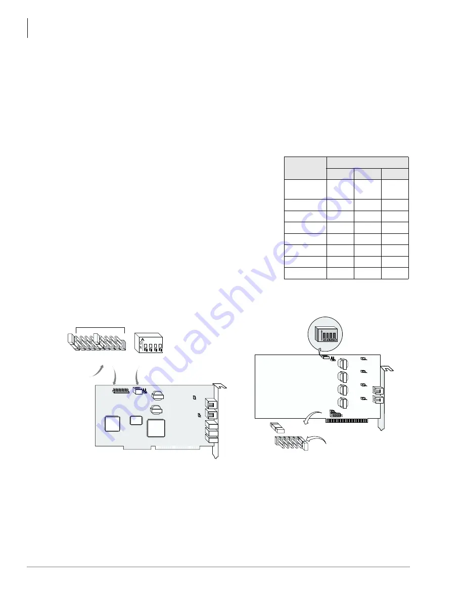
1. Set Interrupt Level – Using the JP1 jumper block set the ProLine/2V or Dialog/4 interrupt 

level to IRQ7.

Note

Set all ProLine/2V and Dialog/4 boards in the system to the same IRQ level.

2. Set Offset Address – Using the SW1 DIP switches 1, 

2 and 3, set the offset address for the ProLine/2V 
board. The default is 0000H (see table at right). 

Important!

Each board in the Stratagy ES must have a 
unique offset address for the system to 
communicate with the board. Do NOT 
duplicate offset addresses.

3. Verify Hookswitch State – SW1 DIP switch 4 must 

be set to Off.

4. Verify that the jumper on JP7 is installed (see figures 

below). If more than one ProLine/2V and Dialog/4 
board is installed in the Stratagy ES, remove the 
jumper on JP7 from all but one of the ProLine/2V or 
Dialog/4 boards.

5. Go to 

Step 4: Install Voice Board(s)

 on 

page 4

 to continue the system installation procedure.

Board 

Number

SW1: DIP Switches

1

2

3

1

(default)

Off

Off

Off

2

Off

Off

On

3

Off

On

Off

4

Off

On

On

5

On

Off

Off

6

On

Off

On

7

On

On

Off

8

On

On

On

3996

SW1

JP1

JP101

JP102

J1

J2

J3

J4

J5

JP7

J5

J6

1 2 3 4

JP7

SW1

JP1

IRQ 2/9

IRQ 3

IRQ 4

IRQ 5

IRQ 7

IRQ 10

IRQ 11

IRQ 12

SW 1:4

SW 1:3

SW 1:2

SW 1:1

Pin position 5 
(counting from 
right to left)

J1

J2

3786

O
N

1

2

3

4

SW1

SW1

JP5

JP6

JP101

JP201

JP301

JP401

JP7

JP1

J2

JP1

IRQ 7

IRQ 6

IRQ 5

IRQ 4

IRQ 3

IRQ 2/9

JP7

Pin Position 1 
(counting from right 
to left)

ProLine/2V Voice Board

Dialog/4 Voice Board

Summary of Contents for C1

Page 1: ...Installation Guide Model C1 Enterprise Server STRATAGY IMPORTANT Installing Technician Please Read This guide contains the essential information for the proper installation of Stratagy ES hardware ...

Page 2: ...ineering or manufacturing methods may warrant Part Number SES IG SYSC1 VA 4025085 Version A December 2001 Copyright 2001 Toshiba America Information Systems Inc Telecommunication Systems Division All rights reserved No part of this manual covered by the copyrights hereon may be reproduced in any form or by any means graphic electronic or mechanical including recording taping photocopying or inform...

Page 3: ...Y OF NON INFRINGEMENT OF THIRD PARTY RIGHTS THE WARRANTY OF YEAR 2000 COMPLIANCE AND THE IMPLIED WARRANTIES OF MERCHANTABILITY AND FITNESS FOR A PARTICULAR PURPOSE THE ENTIRE RISK AS TO THE QUALITY AND PERFORMANCE OF THE SOFTWARE IS WITH YOU NEITHER TAIS NOR ITS SUPPLIERS WARRANT THAT THE FUNCTIONS CONTAINED IN THE SOFTWARE WILL MEET YOUR REQUIREMENTS OR THAT THE OPERATION OF THE SOFTWARE WILL BE ...

Page 4: ...ch defective or missing parts as are causing the malfunction with new or refurbished parts at their option If TAIS or one of its authorized dealers does not replace or repair such parts the retail customer s sole remedy will be a refund of the price charged by TAIS to its dealers for such parts as are proven to be defective and which are returned to TAIS through one of its authorized dealers withi...

Page 5: ... the components in the server Before starting this procedure use an anti static wrist strap to discharge any static electricity you may be carrying 1 Check the packing list on the side of the carton to make sure that you have received all the items 2 Make sure that you have a Phillips screwdriver Step 1 Remove Cover Facing the back panel of the server unlock the latch push up on the cover latch bl...

Page 6: ...e board Do NOT duplicate offset addresses 3 Verify Hookswitch State SW1 DIP switch 4 must be set to Off 4 Verify that the jumper on JP7 is installed see figures below If more than one ProLine 2V and Dialog 4 board is installed in the Stratagy ES remove the jumper on JP7 from all but one of the ProLine 2V or Dialog 4 boards 5 Go to Step 4 Install Voice Board s on page 4 to continue the system insta...

Page 7: ...rd CAUTION If you find a PEB Terminator on the board s XTERM Socket remove it D 41ESC Set the board identification number by turning the rotary switch SW1 shown at right to one of the 16 board ID settings 0 9 A F Begin with 0 and increment setting for each additional board 2 Verify Hookswitch State D 41ESC Verify that the SW2 DIP switch 1 is set to Off shown above right 3 Go to Step 4 Install Voic...

Page 8: ...insure that all other boards and cables are properly seated Step 6 Complete Stratagy ES Hardware Setup 1 Replace the server s cover 2 Connect the following items connections shown at right Keyboard Monitor Mouse SAM Modem s phone jack to a PBX or CO line using RJ11C connectors and cables The hardware portion of this installation is now complete 110V Retaining Plate 6009 Remove screw and lift cover...

Page 9: ... DCM The DCM Main screen displays 3 Highlight the Family in the left hand column and the Model of the board in the right hand column Click Next Family Model Proline Proline 2V D x1D Dialog 4 4 Type a unique name for the voice board Click Next The Properties screen for the board displays shown at right 5 Highlight the Address parameter in the upper portion of the screen From the Value field s pull ...

Page 10: ...m group to identify any problem s 11 Click File then Exit The DCM Main screen closes 12 Go to Step 9 Connect Voice Board s to Telephone Lines on page 7 to continue the system installation procedure D 41ESC Voice Board 1 From the Windows NT click Start Programs Dialogic System Software Dialogic Configuration Manager DCM The DCM Main screen displays 2 From the DCM screen click Action then Auto Detec...

Page 11: ...rify the settings It can be helpful to run the Universal Dialogic Diagnostics Utility in the Dialogic System Software program group to identify any problem s 9 Click File then Exit The DCM Main screen closes 10 Go to Step 9 Connect Voice Board s to Telephone Lines on page 7 to continue the system installation procedure Step 9 Connect Voice Board s to Telephone Lines Note A standard telephone does ...

Page 12: ... you leave this screen displayed on the desktop Step 11 Verify System s Basic Functions Verify that each port works and voice playback and basic auto attendant function Dial the extension number for each port Stratagy ES should for each port Answer and play the default company greeting Thank you for calling greeting 1 in User ID mailbox 990 Continue to play the default caller instructions greeting...

Page 13: ... User Guide for soft key and call record operation 3 Test If it doesn t work go back to Set Voice Board s Hardware Switches on page 2 Data and Speech Highway 6021 ACTU Processor PCB Relay Contact Programmable RCA Jack 600 ohm Page Output MOH BGM Jack Volume Control Up to Four Programmable Serial RS 232 Port Modular Jacks Available Local CTX WinAdmin BSIS 2 Optional Conference SW with PAD AMDS Remo...

Page 14: ...entries with StratagyES listed as the Source for causes of startup failure Check to make sure that Dialogic Service has started Check to make sure that the Stratagy Activation Module SAM is securely connected to the system s parallel port Rebuild the Stratagy ES Package list as directed in Chapter 16 Troubleshooting in the Stratagy ES Release 3 Installation and Maintenance Manual Stratagy ES Servi...

Page 15: ......

Page 16: ... I n c Te l e c o m m u n i c a t i o n S y s t e m s D i v i s i o n 9740 Irvine Blvd Irvine CA 92618 1697 949 583 3700 http telecom toshiba com 2001 Toshiba America Information Systems Inc Printed in U S A Strata is a registered trademark of Toshiba Corporation ...

Reviews: