– 15 –
Installation Manual
EN-29
EN-30
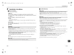
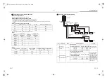
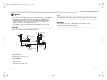
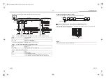
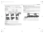
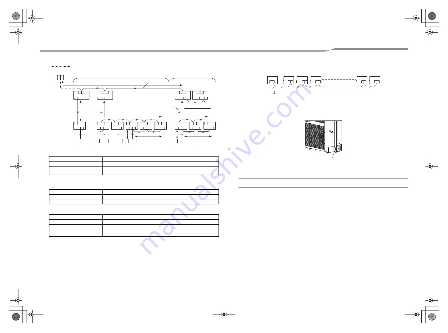
Keep the rule of the following tables about size and length of communication wiring.
Table-1
Control wiring between indoor and outdoor units (L1, L2, L3), Central control wiring (L4)
*1 Total of control wiring length for all refrigerant circuits ( L1 + L2 + L3 + L4 )
Table-2
Control wiring between outdoor units (L5) (Other system)
Table-3
Remote control wiring (L6, L7)
Wiring
2-core, non-polarity
Type
Shield wire
Size / Length *1
AWG16: Up to 3280 ft (1000 m)
AWG14: Up to 6560 ft (2000 m) (*1)
Wiring
2-core, non-polarity
Type
Shield wire
Size / Length
AWG16 to AWG14 / Up to 330 ft (100 m) (L5)
Wiring
2-core
Size
AWG20 to AWG14
Length
• Up to 1640 ft (500 m) (L6 + L7)
• Up 1310 ft (400 m) in case of wireless remote control in group control.
• Up to 660 ft (200 m) total length of control wiring between indoor units (L6)
U3 U4
U1 U2
U1
U3
U2
U4
U1 U2
A B
U3 U4
U1 U2
U1 U2
A B
U1 U2
A B
U1 U2
A B
U1 U2
A B
U1 U2
A B
U3 U4
U1 U2 U5 U6
U1 U2
A B
U1 U2
A B
U1 U2
A B
U3 U4
U1 U2 U5 U6
L1
L5
L6
L6
L7
L7
L4
3
L
2
L
Central
control
This system
Other system
Table-1
Header
unit
Follower
unit
Table-1
Table-2
Table-3
Outdoor unit
Indoor unit
Remote control
Remote control
Remote control
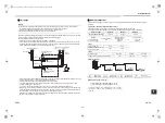
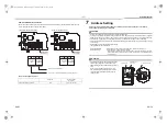
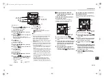
Group control through a remote control
Group control of multiple indoor units (8 units) through a single remote control
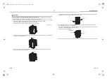
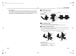
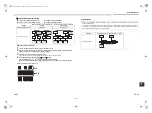
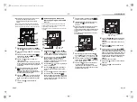
Connection of power wires and communication wires
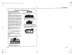
Remove knockouts on the piping / wiring panel or the base and insert the power wires and communication wires
through the holes with the refrigerant piping.
NOTE
Separate the power wire and communication wires.
B
A
B
A
B
A
B
A
B
A
B
A
(A.B)
Indoor unit No.1
No.2
No.3
No.4
No.7
No.8
Remote control
Knockout for the refrigerant piping
+00_EB99809701_00Ta.book Page 15 Tuesday, December 6, 2016 2:07 PM


