background image

Installation Manual

EN

– 22 –

EN-43

EN-44

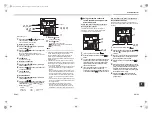
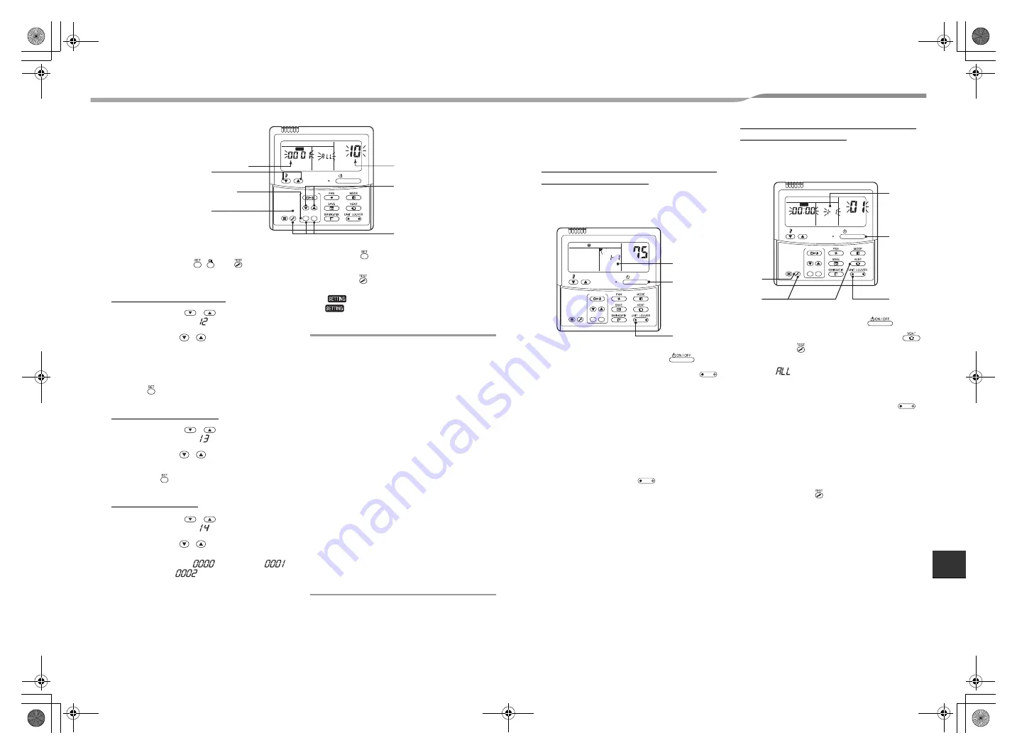
Turn on the power.

1

Push and hold the 

,  , and 

 buttons at the 

same time for more than 4 seconds.

The LCD display will start flashing.

To set-line (system) address

2

Push the TEMP. 


 buttons repeatedly to 

set the CODE No. to 

.

3

Push the TIME 

 / 

 buttons repeatedly to set 

a system address.

(Match the address with the address on the 
interface P.C. board of the header outdoor unit in the 
same refrigerant line.)

4

Push  

button.

(This saves the setting.)

To set-indoor unit address

5

Push the TEMP. 


 buttons repeatedly to 

set the CODE No. to 

.

6

Push the TIME 

 / 

 buttons repeatedly to set 

an indoor unit address.

7

Push the 

 button.

(This saves the setting.)

To set-group address

8

Push the TEMP. 


 buttons repeatedly to 

set the CODE No. to 

.

9

Push the TIME 

 / 

 buttons repeatedly to set 

a group address. If the indoor unit is individual, 
set the address to 

; header unit, 

follower unit, 

.

10

Push the 

 button.

(This saves the setting.)

11

Push the 

 button.

The address setting is complete.
(

 flashes. The unit can be controlled after 

 has disappeared.)

NOTE

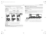
1. Do not use address numbers 

29

 or 

30

 when setting 

system addresses using the remote control.
These 2 address numbers cannot be used on the 
outdoor units and the CODE No. [

E04

] (Indoor/

outdoor communication trouble) will appear if they are 
mistakenly used.

2. If addresses to the indoor units are set in 2 or more 

refrigerate lines manually by using the remote control 
and will control them centrally, set the header outdoor 
unit of each line as below.
• Set a system address for the header outdoor unit of 

each line with SW13 and 14 of their interface P.C. 
boards.

• Turn off dip switch 2 of SW30 on the interface P.C. 

boards of all the header outdoor units connected to 
the same central control, except the unit that has 
the lowest address. (To unify the termination of the 
wiring for the central control of indoor and outdoor 
units.)

• Connect the relay connectors between the [U1, U2] 

and [U3, U4] terminals on the header outdoor unit of 
each refrigerate line.

• After finishing all the settings above, set the 

address of the central control devices. For the 
setting of the central control address, refer to the 
installation manuals of the central control devices.

ON / OFF

TEMP.

TIME

SET CL

FILTER

RESET TEST

TIMER SET

CODE No.

UNIT   No.

SETTING

DATA

SET

R.C.

No.

11

4, 7, 10

2, 5, 8

3, 6, 9

1

SET DATA

CODE No.

Individual

 : 0000

Header unit

 : 0001

In case of group 
control

Follower unit

 : 0002

}}

Using the remote control to 
review the address and position 
of an indoor unit

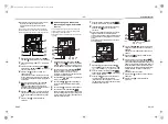
How to determine an indoor unit address if 
the unit position is known.

This instruction works for indoor units that have 
individual, or group control. These steps must be 
performed while the units are operating.

1

If the unit is “OFF” turn it “ON” 

2

Push the left end of the “UNIT LOUVER 

” 

button. 

3

The unit number will be indicated on the control 
LCD as shown above. The numbers disappear 
after a few seconds. The numbers indicate the 
system address and the unit address for the 
indoor unit in question.

4

If 2 or more indoor units are connected to a 
group control, the address for the next 
consecutive unit appears each time the left end 
of the “UNIT LOUVER 

” button is pushed.

How to determine an indoor unit position if 
the unit address is known.

This instruction works for group controlled units only.
These steps must be performed while the units are not 
operating.

1

If the unit is “ON” turn it “OFF” 

2

Simultaneously push and hold the “VENT 

” 

and “TEST 

” buttons for more than 4 

seconds.

3

“ALL 

” appears on the control LCD display. 

The fans and louvers of all the indoor units in 
the control group will be activated.

4

Push the left end of the “UNIT LOUVER 

” 

button.

5

Each time the left side of the button is pushed, 
the next consecutive indoor unit address (in the 
group) will be displayed. While the address is 
displayed, the fan and louvers for that indoor 
unit will operate. For all other units in the group 
the fan and louvers will stop.

6

Push the “TEST 

” button to finish the 

procedure. All the indoor units in the control 
group will stop.

2,4

ON / OFF

TEMP.

TIME

SET CL

FILTER

RESET TEST

TIMER SET

CODE No.

UNIT   No.

No.

°F

1

3

UNIT  LOUVER

UNIT  LOUVER

ON / OFF

TEMP.

TIME

SET CL

FILTER

RESET TEST

TIMER SET

CODE No.

UNIT   No.

SETTING

DATA

SET

R.C.

No.

6
2

3

1

4,5

UNIT  LOUVER

+00_EB99809701_00Ta.book  Page 22  Tuesday, December 6, 2016  2:07 PM

Summary of Contents for Carrier MCY-MAP0367HS-UL

Page 1: ...añol AIR CONDITIONER MULTI TYPE Installation Manual For OUTDOOR USE only Pour une UTILISATION EN EXTÉRIEUR uniquement Solo para USO EXTERIOR Outdoor Unit Model name Heat Pump Model MCY MAP0367HS UL MCY MAP0487HS UL MCY MAP0607HS UL 00_EB99809701_00Ta book Page 1 Tuesday December 6 2016 2 07 PM ...

Page 2: ...rk gloves Keep a quenching cloth and a fire extinguisher nearby during brazing Use care in handling rigging and setting bulky equipment Read these instructions thoroughly and follow all warnings or cautions included in literature and attached to the unit Consult a local building codes and National Electrical Code NEC for special requirements Recognize safety information This is the safety alert sy...

Page 3: ...tion Nitrogen gas must be used for the airtight test Electrical wiring Only a certified installer or qualified service person is allowed to carry out the electrical work of the air conditioner When connecting the electrical wires repairing the electrical parts or undertaking other electrical jobs wear gloves to provide protection for electricians and from heat insulating shoes and clothing to prov...

Page 4: ... are required for the refrigerant R410A as shown in the following table For connecting pipes use new and clean piping materials so that water or dust does not enter Required Tools and Cautions on handling Prepare the tools and equipment listed in the following table before starting the installation work R410A exclusive Generic Tools equipment Use Note Manifold gauge Vacuuming charging refrigerant ...

Page 5: ...r unit to fall which may result in injury This outdoor unit has a weight of about 311 lbs 141 kg Pay special attention when installing the unit onto a wall surface CAUTION Do not install the outdoor unit in a location that is subject to combustible gas leaks Accumulation of combustible gas around the outdoor unit may cause a fire Install the outdoor unit in a location that meets the following cond...

Page 6: ...de panel and wall or other surface of the building for installation and servicing purposes 3 Leave a clearance of at least 7 9 200 between the rear panel and wall or other surface of the building to maintain the air conditioner s performance 19 7 500 Unit in mm 11 8 300 7 9 200 4 Consider the wind direction during the operational season of the air conditioner and install the unit so that the disch...

Page 7: ...f an obstacle in both the front and rear of the unit should be lower than the height of the outdoor unit Standard installation 1 Single unit installation 2 Serial installation of two or more units Serial installation in front and rear Open above and to the right and left of the unit The height of an obstacle in both the front and rear of the unit should be lower than the height of the outdoor unit...

Page 8: ...eg Correct Correct Foundation Absorb vibration with vibration proof rubber pads Foundation Bottom plate of outdoor unit Support the bottom surface of the fixing leg that is in contact with and underneath the bottom plate of the outdoor unit Incorrect If only the end of the fixing leg is supported it may deform Do not support the outdoor unit only with the fixing leg Foundation 0 6 15 mm or less Ti...

Page 9: ...R410A with the conventional flare tool pull the tool out approx 0 02 0 5 mm more than that for R22 to adjust it to the specified flare size The copper pipe gauge is useful for adjusting the projection margin size REQUIREMENT When brazing the refrigerant pipes be sure to use nitrogen gas to prevent oxidation of the inside of the pipes otherwise clogging of the refrigerating cycle due to oxidized sc...

Page 10: ...apacity code No of connectable indoor units Total capacity code of connectable indoor units Equivalent to capacity Min 2 Max 036 type 36 2 to 6 18 48 048 type 48 2 to 8 24 64 060 type 60 2 to 9 30 81 Selection of refrigerant piping No Piping parts Name Selection of pipe size Remarks 1 Outdoor unit 1st branching section Main pipe Size of main pipe Same as the outdoor unit s connecting pipe size 2 B...

Page 11: ...lue ft m Pipes Piping Length Total extension of pipe liquid pipe real length 591 180 L1 L2 L3 a b c d e f Furthest piping length L 1 Real length 328 100 L1 L3 f Equivalent length 410 125 Max equivalent length of main pipe 213 65 L1 Max equivalent length of furthest piping from 1st branching Li 1 115 35 L3 f Max real length of indoor unit connecting pipe 49 15 a b c d e f Height Difference Height b...

Page 12: ...t use Oxygen Flammable gas and Noxious gas in an airtight test To detect a gross leakage 1 Apply pressure 44 psi for 3 minutes or more 2 Apply pressure 218 psi for 3 minutes or more To detect a slow leakage 3 Apply pressure 602 psi for approx 24 hours Check pressure down No pressure down Accepted Pressure down Check the leaked position Main pipe Connected to indoor unit Low pressure gauge High pre...

Page 13: ...and then check that the vacuum does not change If it does change then there may be a leak within the system After the above procedure for vacuuming has finished exchange the vacuum pump with a refrigerant cylinder and advance to the additional charging of refrigerant Main pipe Connected to indoor unit Low pressure gauge High pressure gauge Ball valve fully closed Gas side Flare connection Flare co...

Page 14: ... the gas side Finishing after connecting pipes After the piping connection work has been finished cover the opening of the piping wiring panel with the piping cover or fill silicon or putty in the space between the pipes In case of drawing out the pipes downward or sideward also close the openings of the base plate and the side plate Under the opened condition a problem may be caused due to the en...

Page 15: ...onnection wires Use UL wires rated 300 V for remote control wires Power supply specifications Standard model MCA Maximum Circuit Amps MOCP Maximum Overcurrent Protection Amps Model Power Supply Nominal Voltage Phase and frequency MCA A MOCP A MCY MAP0367HS UL 208 230 V 1 60 Hz 36 3 60 MCY MAP0487HS UL 36 3 60 MCY MAP0607HS UL 36 3 60 Circuit breaker Disconnect per NEC and local codes Communication...

Page 16: ...f control wiring between indoor units L6 U3 U4 U1 U2 U1 U3 U2 U4 U1 U2 A B U3 U4 U1 U2 U1 U2 A B U1 U2 A B U1 U2 A B U1 U2 A B U1 U2 A B U3 U4 U1 U2 U5 U6 U1 U2 A B U1 U2 A B U1 U2 A B U3 U4 U1 U2 U5 U6 L1 L5 L6 L6 L7 L7 L4 3 L 2 L Central control This system Other system Table 1 Header unit Follower unit Table 1 Table 2 Table 3 Outdoor unit Indoor unit Remote control Remote control Remote control...

Page 17: ...nector Power supply wires Communication wires Protection busing 4 Connect the power supply wires and the communication wires to each terminal blocks Use the ring terminals on the field power wires if required by NEC and local codes Screw size and tightening torque Screw size Tightening torque lbf ft N m Power supply terminal M6 1 8 to 2 2 2 5 to 3 0 Ground screw M6 1 8 to 2 2 2 5 to 3 0 Interface ...

Page 18: ...7 segment display on the interface P C board of the outdoor unit until the indoor units are turned on This is not a malfunction It may take up to ten minutes normally about five minutes to address one refrigerant line automatically Settings on the outdoor unit are required for automatic addressing Address setting is not started simply by turning on the power Running the unit is not required for ad...

Page 19: ...rally Address setting procedure To procedure 1 To procedure 2 System wiring diagram Outdoor Outdoor Central control Central control Indoor Indoor Indoor Indoor Remote control Remote control Remote control Outdoor Indoor Remote control Outdoor Central control Indoor Indoor Indoor Remote control Remote control U 1 L08 U 1 flash Auto 1 Auto 2 Auto 3 U 1 U 1 flash U 1 U 1 light 3 2 4 D600 D601 D602 D6...

Page 20: ...m side Interface P C board on the outdoor unit SW06 SW07 SW09 SW10 SW11 SW12 SW13 SW14 1 2 3 4 1 2 3 4 1 2 3 4 1 2 3 4 1 2 3 4 1 2 3 4 1 2 3 4 1 2 3 4 Switch settings for a line system address on the interface P C board on the outdoor unit switch ON switch OFF not used for system address setting Do not change their positions Line system address SW13 SW14 1 2 3 4 1 2 3 4 1 2 3 4 5 6 7 8 9 10 11 12 ...

Page 21: ... off dip switch 2 of SW30 on the interface P C boards of all the outdoor units connected to the same central control except the unit that has the lowest address For unifying the termination of the wiring for the central control of indoor and outdoor units U1 U2 U3 U4 CN02 CN10 U1 U2 U3 U4 TO INDOOR UNIT TO CENTRAL CONTROLLER U1 U2 and U3 U4 not connected Communication terminal board U 1 L08 U 1 fl...

Page 22: ...omatic setting Outdoor unit U1 U2 and U3 U4 connected Outdoor unit U1 U2 and U3 U4 connected Outdoor unit U1 U2 and U3 U4 connected Manual address setting using a remote control This procedure should be used if the indoor unit wiring is completed and the outdoor unit wiring has not been started For this procedure the group remote control should not be connected One individual remote control should...

Page 23: ... the central control devices For the setting of the central control address refer to the installation manuals of the central control devices ON OFF TEMP TIME SET CL FILTER RESET TEST TIMER SET CODENo UNIT No SETTING DATA SET R C No 11 4 7 10 2 5 8 3 6 9 1 SET DATA CODE No Individual 0000 Header unit 0001 In case of group control Follower unit 0002 Using the remote control to review the address and...

Page 24: ...dress to change Repeat steps 4 through 6 to continue changing the indoor unit address and make each of them unique ON OFF TEMP TIME SET CL FILTER RESET TEST TIMER SET CODENo UNIT No SETTING DATA SET R C No 2 7 1 4 6 5 3 UNIT LOUVER SWING FIX UNIT LOUVER 3 5 8 1 4 2 6 7 ON OFF TEMP TIME SET CL FILTER RESET TEST TIMER SET CODENo UNIT No SETTING DATA SET R C No Finish UNIT LOUVER UNIT LOUVER 7 Push t...

Page 25: ... control Remote control Remote control Indoor units to have their addresses initialized Header unit Header unit Central control 8 Test Run CAUTION Turn on the power and turn on the case heater of the compressor To save the compressor when it is activated leave the power on for more than 12 hours Methods of test run A test run is executed by using a remote control Operate the system normally to che...

Page 26: ...dress 1 to 16 1 1 to 16 Set number of SW02 1 to 16 2 17 to 32 Set number of SW02 16 1 to 16 3 33 to 48 Set number of SW02 32 1 to 16 4 49 to 64 Set number of SW02 48 A U1 B 7 segment display B A 7 segment display Address display of the corresponding indoor unit B A 7 segment display Address display of the corresponding indoor unit FF is displayed for 5 seconds A U1 B 7 segment display Collective t...

Page 27: ... F23 Ps sensor trouble F24 Pd sensor trouble F31 Outdoor EEPROM trouble H01 Compressor breakdown A B D600 D601 D602 D603 D604 H02 Compressor trouble Lock H03 Current detective circuit system trouble H06 Low pressure protective operation L04 Outdoor system address duplicated L06 Number of indoor units with priority Duplication of indoor units with priority L08 Indoor group Address unset L10 Outdoor...

Page 28: ...ction device Use the following calculation to determine the correct amount Concentration limit Compliance to the local applicable regulations and standards for the concentration limit is required NOTE 1 If there are 2 or more refrigerating systems in a single refrigerating device the amounts of refrigerant should be as charged in each independent device For the amount of charge in this example The...

Page 29: ...EB99809701 00_EB99809701_00Ta book Page 85 Tuesday December 6 2016 2 07 PM ...

Reviews: