background image

– 20 –

EN

E31

E31

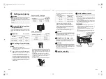
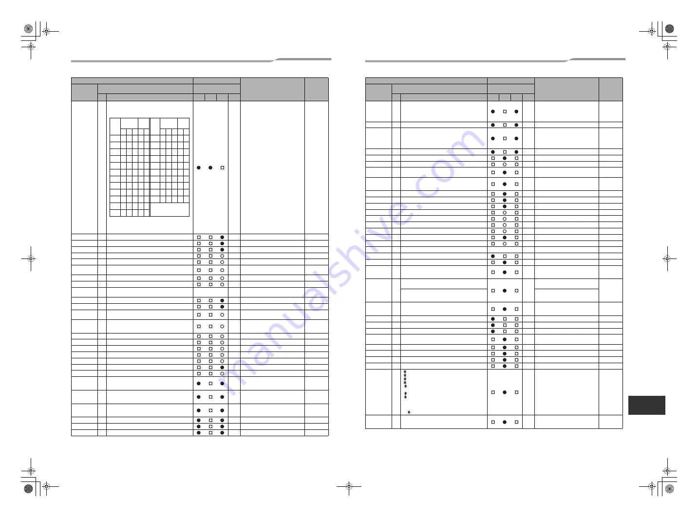
IPDU communication trouble

I/F

F01

ALT Indoor TCJ sensor trouble

Indoor

F02

ALT Indoor TC2 sensor trouble

Indoor

F03

ALT Indoor TC1 sensor trouble

Indoor

F04

F04

ALT TD1 sensor trouble

I/F

F05

F05

ALT TD2 sensor trouble

I/F

F06

F06 TE1 sensor

TE2 sensor

ALT TE1 sensor trouble

TE2 sensor trouble

I/F

F07

F07

ALT TL sensor trouble

I/F

F08

F08

ALT TO sensor trouble

I/F

F09

F09 01: TG1

02: TG2

TG1 sensor trouble

TG2 sensor trouble

I/F

F10

ALT Indoor TA sensor trouble

Indoor

F11

— TF sensor

ALT TF sensor trouble

Indoor

F12

F12 01: TS1 sensor

03: TS3 sensor

ALT TS1 sensor trouble, TS3 sensor trouble

I/F

F13

F13

01: Comp. 1 side

02: Comp. 2 side

03: Comp. 3 side 

ALT TH sensor trouble

IPDU

F15

F15

ALT Outdoor temp. sensor miswiring (TE1, TL)

I/F

F16

F16

ALT Outdoor pressure sensor miswiring (Pd, Ps)

I/F

F22

F22

ALT TD3 trouble

I/F

F23

F23

ALT Ps sensor trouble

I/F

F24

F24

ALT Pd sensor trouble

I/F

F29

SIM Indoor other trouble

Indoor

F31

F31

SIM Indoor EEPROM trouble

I/F

H01

H01

01: Comp. 1 side

02: Comp. 2 side

03: Comp. 3 side

Compressor break down

IPDU

H02

H02

01: Comp. 1 side

02: Comp. 2 side

03: Comp. 3 side

Compressor trouble (lock)

IPDU

H03

H03

01: Comp. 1 side

02: Comp. 2 side

03: Comp. 3 side

Current detect circuit system trouble

IPDU

H05

H05

TD1 miswiring

I/F

H06

H06

Low pressure protective operation

I/F

H07

H07

Oil level down detective protection

I/F

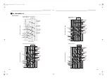
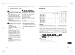
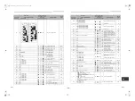
Check code

Wireless remote control

Check code name

Judging 

device

Wired remote 

control display

Outdoor 7-segment display

Sensor block display of 

receiving unit

Auxiliary code

Operation Timer Ready Flash

Sub-

code

A3-IPDU

Fan- 

IPDU Sub-

code

A3-IPDU

Fan- 

IPDU

1 2 3 1 2

1 2 3 1 2

01

0D

 

02

0E

  

03

 

0F

   

04

11

05

12

06

 

13

 

07

  

18

 

08

19

 

09

1A

 

0A

1B

 

 

0B

 

Circle (

): IPDU trouble

0C

 

H08

H08

01: TK1 sensor trouble

02: TK2 sensor trouble

03: TK3 sensor trouble

04: TK4 sensor trouble

05: TK5 sensor trouble

Oil level detective temp sensor trouble

I/F

H15

H15

TD2 miswiring

I/F

H16

H16

01: TK1 oil circuit system trouble

02: TK2 oil circuit system trouble

03: TK3 oil circuit system trouble

04: TK4 oil circuit system trouble

05: TK5 oil circuit system trouble

Oil level detective circuit trouble

I/F

H25

H25

TD3 miswiring

I/F

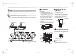
L03

SIM Indoor center unit duplicated

Indoor

L04

L04

SIM Outdoor line address duplicated

I/F

L05

SIM Duplicated indoor units with priority

(Displayed in indoor unit with priority)

I/F

L06

L06 No. of indoor units with priority

SIM

Duplicated indoor units with priority

(Displayed in unit other than indoor unit 

with priority)

I/F

L07

SIM Group line in individual indoor unit

Indoor

L08

L08

SIM Indoor group / Address unset

Indoor, I/F

L09

SIM Indoor capacity unset

Indoor

L10

L10

SIM Outdoor capacity unset

I/F

L17

L17

SIM Outdoor unit model unmatch trouble

I/F

L20

SIM Duplicated central control addresses

Indoor

L28

L28

SIM Over No. of connected outdoor units

I/F

L29

L29 The same as E31

SIM No. of IPDU trouble

I/F

L30

L30 Detected indoor address

SIM Indoor outside interlock

Indoor

L31

Extended I/C trouble

I/F

P01

ALT Indoor fan motor trouble

Indoor

P03

P03

ALT Discharge temp. TD1 trouble

I/F

P04

P04

01: Comp. 1 side

02: Comp. 2 side

03: Comp. 3 side

ALT High-pressure SW system operation

IPDU

P05

P05

00: Detected phase loss

ALT

Phase loss trouble / interruption of 

power supply

I/F

01: Comp. 1 side

02: Comp. 2 side

03: Comp. 3 side

Inverter DC voltage (Vdc) trouble

P07

P07

01: Comp. 1 side

02: Comp. 2 side

03: Comp. 3 side

ALT Heat sink overheat trouble

IPDU, I/F

P10

P10 Detected indoor address

ALT Indoor overflow trouble

Indoor

P12

ALT Indoor fan motor trouble or duct setting miss

Indoor

P13

P13

ALT Outdoor liquid back detection trouble

I/F

P15

P15 01: TS condition

02: TD condition

ALT Gas leak detection

I/F

P17

P17

ALT Discharge temp. TD2 trouble

I/F

P18

P18

ALT Discharge temp. TD3 trouble

I/F

P19

P19 Detected outdoor unit number

ALT 4-way valve inverse trouble

I/F

P20

P20

ALT High-pressure protective operation

I/F

P22

P22

0

: IGBT circuit

1

: Location detection circuit trouble

3

: Motor lock-up trouble

4

: Motor current was detected.

C

: Abnormal temperature was detected by the TH 

sensor.

D

: TH sensor trouble

E

: Inverter DC voltage trouble (outdoor unit fan)

Caution)

Although letters 0 to F appear at locations indicated 

by “ ”, please ignore them.

ALT Outdoor fan IPDU trouble

IPDU

P26

P26

01: Comp. 1 side

02: Comp. 2 side

03: Comp. 3 side

ALT G-TR short protection trouble

IPDU

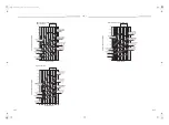
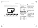
Check code

Wireless remote control

Check code name

Judging 

device

Wired remote 

control display

Outdoor 7-segment display

Sensor block display of 

receiving unit

Auxiliary code

Operation Timer Ready Flash

39-EN

40-EN

+00EB99808801_01EN.book  Page 20  Monday, April 11, 2016  2:30 PM

Summary of Contents for Carrier MMD-AP0074BH2UL-1

Page 1: ...P0304BH2UL 1 MMD AP0364BH2UL 1 MMD AP0424BH2UL 1 MMD AP0484BH2UL 1 Indoor Unit Model name Medium Static Ducted Type MMD AP0074BH2UL 1 MMD AP0094BH2UL 1 MMD AP0124BH2UL 1 MMD AP0214BH2UL 1 MMD AP0154BH2UL 1 MMD AP0184BH2UL 1 AIR CONDITIONER MULTI TYPE Installation Manual 00EB99808801_01EN book Page 1 Monday April 11 2016 2 30 PM ...

Page 2: ...ent from the one specified for complement or replacement Otherwise abnormally high pressure may be generated in the refrigeration cycle which may result in a failure or explosion of the product or an injury to your body Connect ground wire grounding work Incomplete grounding may cause an electric shock Do not connect ground wires to gas pipes water pipes lightning rods or ground wires for telephon...

Page 3: ...not enter the refrigerating cycle To prevent charging an incorrect refrigerant and refrigerating oil the sizes of connecting sections of charging port of the main unit and installation tools are changed from those for the conventional refrigerant Accordingly the exclusive tools are required for the new refrigerant R410A For connecting pipes use new and clean piping designed for R410A and please ca...

Page 4: ...uencies are generated by inverter equipment in house power generators medical equipment or communication equipment Malfunctioning or control trouble in the air conditioner or noise may adversely affect the equipment s operation Locations where there is anything under the unit installed that would be compromised by wetness If the drain has become blocked or when the humidity is over 80 condensation...

Page 5: ... opening size C 29 5 750 41 3 1050 55 1 1400 Space required for attaching or detaching the filter D 28 7 730 23 6 600 40 5 1030 Electrical control box Air filter locally procured 5 9 150 Ceiling opening size 15 5 400 Min 1 Air discharge Ceiling opening size C Electrical control box Check port A 17 7 17 7 450 450 Air discharge 5 9 150 or more Air intake 1 2 30 Ceiling Ceiling Unit width 31 5 800 Ce...

Page 6: ... band at positions other than specified To install vibration isolation material to hanging bolts confirm that it does not increase the unit vibration External dimensions Unit in mm CORRECT INCORRECT INCORRECT 1 room Hanging bolt 4 M0 4 10 locally procured Hanging bolt pitch B Unit external dimension A Air discharge flange outside C 5 5 140 1 7 44 1 9 49 Outside 8 6 218 2 5 8 147 5 Air filter slot ...

Page 7: ...tallation of the wired remote control refer to the instructions that are supplied with the control The connection point for the control wiring and the entrance point for the control wiring are clearly marked in the instructions Hanging bolt W3 8 M10 4 pieces Nut W3 8 M10 12 pieces Nut W3 8 M10 M10 flat washer Accessory M10 flat washer Accessory Hanging bolt W3 8 M10 Nut W3 8 M10 Set the air intake...

Page 8: ...pressure Fan speed Low Standard Air flow 556cfm Air flow rate lower limit Air flow rate upper limit High static pressure 3 Fan speed Low 0 000 0 050 0 100 0 150 0 200 0 250 0 300 0 350 0 400 0 450 0 500 0 550 400 450 500 550 600 650 700 750 800 850 MMD AP0214BH2UL 1 MMD AP0244BH2UL 1 MMD AP0304BH2UL 1 Air flow rate cfm External static pressure in WG High static pressure 3 About 0 46 in WG Fan spee...

Page 9: ...Standard static pressure About 0 25 in WG Fan speed High Low static pressure About 0 15 in WG Fan speed High High static pressure 3 Fan speed Low Max Air flow point High static pressure 3 Fan speed Low High static pressure 1 Fan speed Low Low static pressure Fan speed Low Standard Air flow 304cfm Air flow rate lower limit Air flow rate upper limit Under air intake Standard static pressure Fan spee...

Page 10: ...tic pressure 1 About 0 35 in WG Fan speed High Standard static pressure About 0 25 in WG Fan speed High Low static pressure About 0 15 in WG Fan speed High High static pressure 1 Fan speed Low Standard static pressure Fan speed Low Low static pressure Fan speed Low Standard Air flow 1000cfm Air flow rate lower limit Air flow rate upper limit High static pressure 3 Fan speed Low MMD AP0424BH2UL 1 M...

Page 11: ... piece 12 18 1 1 piece 12 25 1 1 piece D H 12 6 320 Remove this cover to install filters in the filter rack Replace the cover after the filters are installed Filter rack W All unit models have the FR 1 FR 2 filter position option available Both positions use the same filters per model shown in the chart above Two positions for filter rack FR 1 FR 2 Indoor unit FR 1 Back air intake flange FR 2 Unde...

Page 12: ...s shown in the following figure Do not provide any air vents Otherwise the drain water will spout causing water to leak Do not allow any force to be applied to the connection area with the drain pipe Connecting drain pipe Insert the drain socket into the connector until the socket can go no farther REQUIREMENT Connect the hard vinyl chloride pipes certainly so that water does not leak by using adh...

Page 13: ...rts running Check whether the water is draining from the drain pipe connecting port and check that no water is leaking from the drain pipe After checking that the water drains and there are no water leaks turn off the power connect the float switch connector to its original location CN80 on the printed circuit board and return the electrical control box to its original position When gravity draina...

Page 14: ... 8 15 9 0 78 19 7 B A Work using double spanner Use the tightening torque levels as listed in the following table Tightening torque of flare pipe connections Pressure of R410A is higher than that of R22 Approx 1 6 times Therefore using a torque wrench tighten the flare pipe connecting sections which connect the indoor and outdoor units of the specified tightening torque Incorrect connections may c...

Page 15: ... it is dangerous because overheat or seizure may be caused Indoor unit power supply For the power supply of the indoor unit prepare the exclusive power supply separated from that of the outdoor unit Power supply Control wiring Central control wiring 2 core with non polarity wires are used for the control wiring between indoor unit and outdoor unit and Central control wiring To prevent noise troubl...

Page 16: ...ow voltage circuit is provided for the remote control Do not connect the high voltage circuit Remove the cover of the electrical control box by taking off the mounting screws 3 positions Attach the conduit pipe with a lock nut Tighten the screws of the terminal block and fix the wires with cord clamp attached to the electrical control box Do not apply tension to the connecting section of the termi...

Page 17: ...ear the display content and repeat the procedure from the beginning No operation of the remote control is accepted for a while after button is pushed While air conditioners are operated under the group control ALL is displayed first When is pushed the indoor unit number displayed following ALL is the header unit 1 6 1 3 2 5 4 Display content varies with the indoor unit model 2 Each time button is ...

Page 18: ...the basic operation procedure 1 2 3 4 5 6 For the CODE No in Procedure 3 specify 06 For the set data in Procedure 4 select the SET DATA of shift value of detection temperature to be set up from the following table Remote control sensor The temperature sensor of the indoor unit senses room temperature usually Set the remote control sensor to sense the temperature around the remote control Select it...

Page 19: ...e selection of mode in the test mode is permitted 2 Push button 3 Select the operation mode with button Cool or Heat Do not run the air conditioner in a mode other than Cool or Heat The temperature controlling function does not work during test run The detection of trouble is performed as usual 4 After the test run push button to stop a test run Display part is same as procedure 1 5 Push button to...

Page 20: ...emote control See Wired remote control display in the list To check from outdoor unit See Outdoor 7 segment display in the list To check from indoor unit with a wireless remote control See Sensor block display of receiving unit in the list IPDU Intelligent Power Drive Unit Lighting Flashing Goes off ALT Flashing is alternately when there are two flashing LED SIM Simultaneous flashing when there ar...

Page 21: ...d Indoor L04 L04 SIM Outdoor line address duplicated I F L05 SIM Duplicated indoor units with priority Displayed in indoor unit with priority I F L06 L06 No of indoor units with priority SIM Duplicated indoor units with priority Displayed in unit other than indoor unit with priority I F L07 SIM Group line in individual indoor unit Indoor L08 L08 SIM Indoor group Address unset Indoor I F L09 SIM In...

Page 22: ...installation procedure so that if the refrigerant accidentally leaks out its concentration does not reach the limit and in the event of an emergency measures can be made before injury can occur In a room where the concentration may exceed the limit create an opening with adjacent rooms or install mechanical ventilation combined with a gas leak detection device The concentration is as given below T...

Page 23: ...qualifié ou une personne d entretien est autorisé à procéder à l installation Une installation inadéquate peut se solder par une fuite d eau une électrocution ou un incendie N utilisez pas un fluide frigorigène différent de celui spécifié pour le complément ou le remplacement Faute de quoi une pression anormalement élevée risque d être générée dans le circuit de réfrigération ce qui peut entraîner...

Page 24: ... le fluide frigorigène précédent ou l huile réfrigérante n entrent pas dans le circuit de réfrigération Pour éviter de remplir du fluide réfrigérant et de l huile réfrigérante inappropriés la taille des sections de raccordement de l orifice de remplissage de l unité principale et les outils d installation sont différents de ceux qui sont utilisés pour le fluide frigorigène traditionnel En conséque...

Page 25: ...erseurs des groupes électrogènes internes du matériel médical ou de communication Un dysfonctionnement un mauvais contrôle du climatiseur ou un bruit au niveau de ce dernier pourrait nuire au bon fonctionnement de l équipement Les endroits dans lesquels le climatiseur serait installé au dessus d objets que l humidité pourrait détériorer Si la conduite de vidange est obstruée ou si le taux d humidi...

Page 26: ...08 305 Dimension d ouverture du plafond C 29 5 750 41 3 1050 55 1 1400 Espace nécessaire pour attacher ou détacher le filtre D 28 7 730 23 6 600 40 5 1030 Boîtier de commande électrique Filtre à air vendu sur place 5 9 150 Taille de l ouverture au plafond 15 5 400 Min 1 Evacuation d air Dimension d ouverture du plafond C Boîtierdecommande électrique Trappe d inspectionA 17 7 17 7 450 450 Evacuatio...

Page 27: ...és Avant d appliquer le matériau d isolement aux vibrations sur les boulons de fixation vérifiez que cela n augmente pas le niveau de vibration de l unité Dimensions extérieures Unité pouce mm Correct Incorrect Incorrect 1 pièce Tiges filetées pour suspension 4 M0 4 10 vendues sur place Distance entre les tiges filetées pour suspension B Dimensions de l unité extérieure A Bride extérieure d évacua...

Page 28: ... télécommande câblée reportez vous aux instructions fournies avec la commande Le point de connexion pour le câblage de la télécommande et le point d entrée pour le câblage de télécommande sont clairement marqués dans le manuel d instructions Tige filetée pour suspension W3 8 M10 4 pièces Ecrou W3 8 M10 12 pièces Ecrou W3 8 M10 Rondelle plate M10 Accessoire Rondelle plate M10 Accessoire Tige fileté...

Page 29: ...e de ventilateur Faible Débit d air standard 556 cfm Limite inférieure du débit d air Limite supérieure du débit d air Pression statique élevée 3 Vitesse de ventilateur Faible 0 000 0 050 0 100 0 150 0 200 0 250 0 300 0 350 0 400 0 450 0 500 0 550 400 450 500 550 600 650 700 750 800 850 MMD AP0214BH2UL 1 MMD AP0244BH2UL 1 MMD AP0304BH2UL 1 Débit d air cfm pieds cube par minute Pression statique ex...

Page 30: ...entilateur Élevée Pression statique faible environ 0 15 in WG Vitesse de ventilateur Élevée Pression statique élevée 3 Vitesse de ventilateur Faible Point de débit d air maximum Pression statique élevée 3 Vitesse de ventilateur Faible Pression statique élevée 1 Vitesse de ventilateur Faible Pression statique faible Vitesse de ventilateur Faible Débit d air standard 304 cfm Limite inférieure du déb...

Page 31: ...e de ventilateur Élevée Pression statique standard environ 0 25 in WG Vitesse de ventilateur Élevée Pression statique faible environ 0 15 in WG Vitesse de ventilateur Élevée Pression statique élevée 1 Vitesse de ventilateur Faible Pression statique standard Vitesse de ventilateur Faible Pression statique faible Vitesse de ventilateur Faible Débit d air standard 1000 cfm Limite inférieure du débit ...

Page 32: ...couvercle pour installer les filtres dans la chambre de filtration Replacez le couvercle une fois que les filtres sont installés Support de filtre W Tous les modèles d unité ont une position de filtre optionnel FR 1 FR 2 disponible Les deux positions utilisent les même filtre par modèle indiqués dans le tableau ci dessus Deux positions pour la chambre de filtration FR 1 FR 2 Unité intérieure FR 1 ...

Page 33: ...t battement Installez le réseau de conduites comme illustré dans le schéma suivant Ne formez pas d évents d aération Sinon l eau de vidange jaillira par ces orifices et fuira N appliquez aucune pression sur la zone de raccordement de la conduite de vidange Raccordement du tuyau d évacuation Insérez la conduite de vidange au niveau de la conduite autant que possible CARACTÉRISTIQUES REQUISES Raccor...

Page 34: ... vidange et qu aucune fuite n y est observée Après avoir vérifié l évacuation correcte de l eau et l absence de fuite mettez l appareil hors tension branchez le connecteur du flotteur à son emplacement d origine CN80 sur la carte de circuit imprimé puis replacez le boîtier de commandes électriques Quand la vidange à gravité ne peut pas être obtenue directement à partir de la sortie de condensation...

Page 35: ...les de serrage indiqués dans le tableau suivant Couple de serrage des raccords des tuyaux évasés La pression du R410A est supérieure à celle du R22 Environ 1 6 fois En conséquence utilisez une clé dynamométrique et serrez les raccords coniques des sections de raccordement des unités intérieure et extérieure aux couples prescrits Si le raccordement n est pas correct une fuite de gaz est possible et...

Page 36: ... faible c est dangereux car une surchauffe ou un grippage peut se produire Alimentation de l unité intérieure Pour l alimentation électrique de l unité intérieure préparez l alimentation électrique exclusive séparée de celle de l unité extérieure Alimentation Câblage de commande câblage de commande centralisée Des câbles 2 conducteurs sans polarité sont utilisés pour le câblage de commande entre l...

Page 37: ... de l unité intérieure La télécommande est alimentée en basse tension Ne raccordez pas le circuit haute tension Retirez le couvercle du boîtier de commandes électriques en dévissant pour cela les vis de montage 3 positions Attachez la conduite avec un contre écrou Serrez les vis de la plaquette de connexion puis fixez les câbles avec le serre fil fourni avec le boîtier des commandes électriques Ne...

Page 38: ...urant les quelques minutes qui suivent l enfoncement de la touche Quand les climatiseurs fonctionnent en commande centralisée l indication ALL s affiche en premier Quand vous appuyez sur la touche le numéro de l unité intérieure suivi de ALL qui s affiche est l unité principale 1 6 1 3 2 5 4 Le contenu de l afficheur varie selon le modèle de l unité intérieure 2 Chaque pression sur la touche chang...

Page 39: ... 2 3 4 5 6 Pour le CODE No dans la Procédure 3 spécifiez 06 Pour les données définies de la procédure 4 sélectionnez le SET DATA de la valeur seuil de la température dans le tableau suivant Capteur de télécommande En principe le capteur de température de l unité intérieure détecte la température de la pièce Réglez le capteur de télécommande pour qu il détecte la température autour de la télécomman...

Page 40: ...r la touche 3 À l aide de la touche sélectionnez le mode de fonctionnement Refroidissement ou Chauffage Ne faites pas fonctionner le climatiseur dans un mode autre que Refroidissement ou Chauffage La fonction de commande de température est désactivée durant l essai de fonctionnement La détection de problèmes est exécutée comme d habitude 4 Après l essai de fonctionnement appuyez sur la touche pour...

Page 41: ...rôle à partir de l unité extérieure Reportez vous à Écran à 7 bâtonnets extérieur dans la liste Contrôle à partir d une unité intérieure avec une télécommande sans fil Reportez vous à Bloc de capteurs de l unité de réception dans la liste IPDU Bloc d entraînement intelligent Éclairé Clignote S éteint ALT Le clignotement est alternatif quand il y a deux LED qui clignotent SIM Le clignotement est si...

Page 42: ...double Intérieure L04 L04 SIM Adresse de ligne extérieure en double I F L05 SIM Unités intérieures avec priorité en double Affiché pour les unités intérieures avec priorité I F L06 L06 Nombre d unités intérieures avec priorité SIM Unités intérieures avec priorité en double Affiché pour les unités autres que les unités intérieures avec priorité I F L07 SIM Ligne de groupe dans une unité intérieure ...

Page 43: ...le qui convient et l installation adaptée pour qu en cas de fuite la concentration n atteigne pas la limite et qu en cas d urgence les mesures puissent être prises avant l accident Dans une pièce où la concentration peut excéder la limite créez une ouverture sur les pièces voisines ou installez une ventilation mécanique associée à un détecteur de fuite de gaz La concentration est donnée ci dessous...

Page 44: ... HIGH STATIC 1 0001 HIGH STATIC 2 0003 LOW STATIC 0006 Have you changed lighting time of filter sign If not fill check mark in NO CHANGE and fill check mark in ITEM if changed respectively For check method refer to Applicable controls in this manual Filter sign lighting time CODE No 01 NO CHANGE NONE 0000 150H 0001 2500H 0002 5000H 0003 10000H 0004 Filter sign lighting time CODE No 01 NO CHANGE NO...

Reviews: