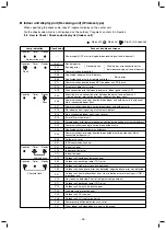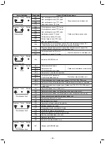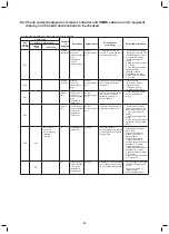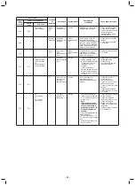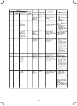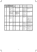
L10
L10
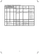
I/F
Outdoor
capacity not set
All stop
Jumper wire provided on P.C.
board for servicing I/F P.C.
board has not been removed
as required for given model.
Check model setting of P.C.
board for servicing outdoor
I/F P.C. board.
L17
L17
Target indoor
address
I/F
Outdoor unit
model mismatch
error
The outdoor unit model is
duplicate. The Cool/Heat
Flex series 1/2 are duplicate.
Check the outdoor unit
model.
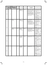
L18
L18
I/F
Cool / heat
switch unit error
Only the target
unit stopped
The heating operation was
performed without the cool-
only setting configured in a
cool-only room where a cool/
heat switch unit is not
connected.
Check the remote controller
setting. (DN="0F")
Check the cool / heat
switching unit.
Check the piping connection
of the switching unit.
(Miswiring of discharge gas /
suction gas)
Check the SVS / SVD valve
miswiring / misinstallation.
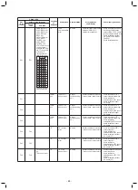
L20
AI-NET
Indoor
unit
Duplicated
central control
address
All stop
There is duplication in central
control address setting.
Check central control
addresses.
Check network adaptor
P.C. board (applicable to
AI-NET).
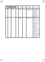
L28
L28
I/F
Too many
outdoor units
connected
All stop
There are more than four
outdoor units.
Check No. of outdoor units
connected (Only up to 4
units per system allowed).
Check communication
lines between outdoor
units.
Check for defect in outdoor
P.C. board (I/F).
L29
L29
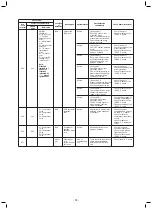
SMMS (Series 1)
01: A3-IPDU1
error
02: A3-IPDU2
error
03: A3-IPDU1/A3-
IPDU2 error
04: Fan IPDU
error
05: A3-IPDU1 +
Fan IPDU error
06: A3-IPDU2 +
Fan IPDU error
07: All IPDU error
or Communication
error between
IPDU and I/F
circuit board or
Outdoor I/F circuit
board error
I/F
Error in No. of
IPDUs
All stop
Insufficient number of IPDUs
are detected when power is
turned on.
Check model setting of
P.C. board for servicing
outdoor I/F P.C. board.
Check connection of UART
communication connector.
Check A3-IPDU, fan IPDU,
and I/F P.C. board for
defect.
SM
(Series 4)
A3-IPDU Fan
IPDU
Symbol O signifies
site of IPDU error.
01
02
03
04
05
06
07
08
09
0A
0B
0C
0D
0E
0F
1 2 3
MS-i
Check code
Location
of
detection
Description
System status
Error detection
condition(s)
Check items (locations)
Outdoor 7-segment display
Sub-code
Check
code
Main
remote
controller
- 72 -
Summary of Contents for Carrier MMU-AP0074HPUL
Page 15: ...2 WIRING DIAGRAM 15 ...


