background image

R410A

FILE NO. A09-010-2

Revised : Feb. 2010

PRINTED IN JAPAN, Dec., 2009   ToMo

SERVICE MANUAL

SPLIT TYPE

REVISION 2 : Jan.2012

Re-edit version.( file volume down)

Contents have NOT been changed.

OUTDOOR UNIT

<SUPER DIGITAL INVERTER>

RAV-SP180AT2-UL 

(2 HP)

RAV-SP240AT2-UL 

(3 HP)

RAV-SP300AT2-UL 

(4 HP)

RAV-SP360AT2-UL 

(4, 5 HP)

RAV-SP420AT2-UL 

(5 HP)

Summary of Contents for CARRIER RAV-SP180AT2-UL

Page 1: ... 2009 ToMo SERVICE MANUAL SPLIT TYPE REVISION 2 Jan 2012 Re edit version file volume down Contents have NOT been changed OUTDOOR UNIT SUPER DIGITAL INVERTER RAV SP180AT2 UL 2 HP RAV SP240AT2 UL 3 HP RAV SP300AT2 UL 4 HP RAV SP360AT2 UL 4 5 HP RAV SP420AT2 UL 5 HP ...

Page 2: ...frigerant R22 in order to prevent destruction of the ozone layer WARNING Cleaning of the air filter and other parts of the air filter involves dangerous work in high places so be sure to have a service person do it Do not attempt it yourself The cleaning diagram for the air filter is there for the service person and not for the customer ...

Page 3: ... R410A 23 6 1 Safety During Installation Servicing 23 6 2 Refrigerant Piping Installation 23 6 3 Tools 27 6 4 Recharging of Refrigerant 27 6 5 Brazing of Pipes 28 7 CIRCUIT CONFIGURATION AND CONTROL SPECIFICATIONS 30 7 1 Print Circuit Board MCC 1571 30 7 2 Outline of Main Controls 32 8 TROUBLESHOOTING 45 8 1 Summary of Troubleshooting 45 8 2 Troubleshooting 47 9 REPLACEMENT OF SERVICE P C BOARD 74...

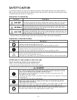
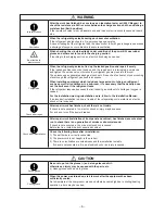
Page 4: ...r work when an incorrect work has been executed Mark Explanation Indicates prohibited items Forbidden items to do The sentences near an illustrated mark describe the concrete prohibited contents Indicates mandatory items Compulsory items to do The sentences near an illustrated mark describe the concrete mandatory contents Indicates cautions Including danger warning The sentences or illustration ne...

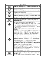
Page 5: ...ed from one of the former R22 For an air conditioner which uses R410A never use other refrigerant than R410A For an air conditioner which uses other refrigerant R22 etc never use R410A If different types of refrigerant are mixed abnormal high pressure generates in the refrigerating cycle and an injury due to breakage may be caused Do not charge refrigerant additionally If charging refrigerant addi...

Page 6: ...t even if the refrigerant leaks If the refrigerant leaks and exceeds the limit density an accident of shortage of oxygen is caused For the installation moving reinstallation work follow to the Installation Manual If an incorrect installation is done a trouble of the refrigerating cycle water leak electric shock or fire is caused After repair work has finished check there is no trouble If check is ...

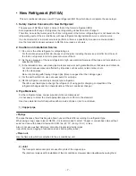
Page 7: ... not mix in because pipes are affected by impurities such as water oxide scales oil etc Use the clean pipes Be sure to brazing with flowing nitrogen gas Never use gas other than nitrogen gas 4 For the earth protection use a vacuum pump for air purge 5 R410A refrigerant is azeotropic mixture type refrigerant Therefore use liquid type to charge the refrigerant If using gas for charging composition o...

Page 8: ...erve also for R22 are necessary as the general tools 1 Vacuum pump Use vacuum pump by attaching vacuum pump adapter 2 Torque wrench 8 Spanner or Monkey wrench 3 Pipe cutter 9 Hole core drill 4 Reamer 10 Hexagon wrench Opposite side 4mm 5 Pipe benderr 11 Tape measure 6 Level vial 12 Metal saw 7 Screwdriver Also prepare the following equipments for other installation method and run check 1 Clamp met...

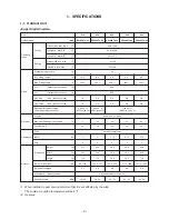
Page 9: ... lbs Refrigerant charged Appearance Munsell symbol Sound Pressure dBa 018 024 030 036 042 SP180AT2 UL SP240AT2 UL SP300AT2 UL SP360AT2 UL SP420AT2 UL 23 to 109 4 69 8 to 89 6 59 to 75 2 4 to 59 59 to 86 25 16 5 16 5 9 8 9 8 9 8 164 1 164 1 246 1 246 1 246 1 98 5 98 5 1 2 5 8 5 8 5 8 5 8 1 4 3 8 3 8 3 8 3 8 0 22 oz ft 0 43 oz ft 0 43 oz ft 65 7 ft to164 1 ft 98 5 ft to 164 1 ft 98 5 ft to 246 1 ft ...

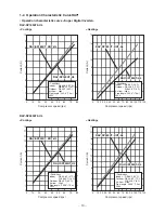
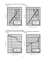
Page 10: ...0CT KRT UL RAV SP240CT KRT UL RAV SP240UT UL RAV SP240UT UL RAV SP240UT UL RAV SP240UT UL RAV SP240CT KRT UL RAV SP240CT KRT UL RAV SP240UT UL RAV SP240UT UL RAV SP240AT2 UL Cooling Heating Compressor speed rps 0 20 10 30 40 50 60 70 80 0 10 9 8 7 6 5 3 4 2 1 Current A Current A 0 16 14 12 8 10 6 4 2 0 20 30 10 40 50 60 70 80 90 100 110 120 Compressor speed rps Conditions Indoor DB 80 6 F 27 C WB ...

Page 11: ...AT2 UL RAV SP420AT2 UL RAV SP420AT2 UL RAV SP300AT2 UL RAV SP360AT2 UL RAV SP420AT2 UL RAV SP300AT2 UL RAV SP360AT2 UL RAV SP420AT2 UL Capacity variation ratio according to temperature RAV SP180AT2 UL RAV SP240AT2 UL RAV SP300AT2 UL RAV SP360AT2 UL RAV SP420AT2 UL Cooling Heating 50 55 60 65 70 75 80 85 90 95 100 105 89 6 32 91 4 33 93 2 34 95 35 96 8 36 98 6 37 100 4 38 102 2 39 104 40 105 8 41 1...

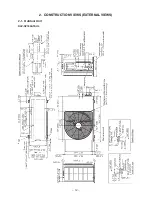
Page 12: ... 12 2 CONSTRUCTION VIEWS EXTERNAL VIEWS 2 1 Outdoor Unit RAV SP180AT2 UL ...

Page 13: ... 13 RAV SP240AT2 UL ...

Page 14: ... 14 RAV SP300AT2 UL RAV SP360AT2 UL RAV SP420AT2 UL ...

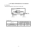
Page 15: ...ing TCJ sensor TC sensor Air heat exchanger To outdoor unit To outdoor unit 3 SYSTEMATIC REFRIGERATING CYCLE DIAGRAM 3 1 Indoor Unit Single type Combination of 1 indoor unit and 1 outdoor unit Dimension table Indoor unit RAV SP180AT2 UL RAV SP240 300 360 420AT2 UL Outer diameter of refrigerant pipe Gas side ØA Liquid side ØB 1 2 12 7 1 4 6 4 5 8 15 9 3 8 9 5 ...

Page 16: ...4 93 2 0 4 78 18 34 18 Compressor drive revolution frequency rps 58 65 30 64 30 88 Indoor fan HIGH HIGH LOW HIGH LOW HIGH Indoor Outdoor temp conditions DB WB F C Indoor Outdoor 80 6 66 2 95 27 19 35 89 6 75 2 109 4 32 24 43 64 4 59 9 23 18 15 5 5 68 44 6 42 8 20 7 6 86 75 2 64 4 30 24 18 59 5 15 15 TE sensor TO sensor TS sensor TD sensor Heat exchanger Ø8 ripple 2 rows 20 stages FP1 3 flat fin Ac...

Page 17: ... load Pressure psi MPa Pd Ps Pd Ps 404 6 129 1 2 79 0 89 511 9 155 2 3 53 1 07 248 0 104 4 1 71 0 72 384 3 98 6 2 65 0 68 464 0 161 0 3 2 1 11 337 9 30 5 2 33 0 21 Pipe surface temperature F C Discharge Suction Indoor heat Outdoor heat exchanger exchanger TD TS TC TE 158 0 55 4 51 8 102 2 70 13 11 39 177 8 62 6 57 2 118 4 81 17 14 48 107 6 44 6 37 4 64 4 42 7 3 18 165 2 39 2 111 2 37 4 74 4 44 3 1...

Page 18: ...changer TD TS TC TL TE 150 8 57 2 53 6 111 2 104 0 66 14 12 44 38 172 4 48 2 55 4 120 2 109 4 78 9 13 49 43 114 8 44 6 41 0 89 6 77 0 46 7 5 32 25 149 0 37 4 102 2 35 6 37 4 65 3 39 2 3 163 4 66 2 129 2 57 2 59 0 73 19 54 14 15 188 6 5 100 4 6 8 8 6 87 15 38 14 13 Compressor drive revolution frequency rps 38 53 21 43 26 71 Indoor fan HIGH HIGH LOW HIGH LOW HIGH Indoor Outdoor temp conditions DB WB...

Page 19: ...6 P33 P20 P21 P22 P23 P24 P25 YEL YEL BRN YEL ORN DB01 DB02 Relay Q404 Q200 205 IGBT Q300 305 MOS FET R221 RED Compressor WHI BLK P04 P05 P06 2 1 2 3 3 1 1 2 1 2 2 3 2 1 1 3 5 6 4 4 6 2 3 2 1 1 3 2 3 1 1 2 2 1 1 3 2 3 1 1 3 CM CN300 CN700 CN603 CN602 CN601 CN600 CN500 BLK WHI ORN 49C BLK RED Fan motor FM Pulse motor valve PMV HP SW R220 R219 L03 C13 C12 C14 R321 R320 R319 Surge absorber F03 Fuse T...

Page 20: ...50V Fuse F01 T25A 250V L1 L2 L1 L2 S L1 L2 S Outdoor unit Indoor unit Earth screw Power supply 208 230 1 60 Earth screw Earth screw 3 5 5 3 20SF PMW 2 3 4 1 ON 2 3 4 SW804 SW801 SW800 1 ON 2 3 4 1 indicates the terminal block Alphanumeric characters in the cycle indicate the terminal No 2 The two dot chain line indicates the wiring procured locally 3 indicates the P C board 4 For the indoor unit c...

Page 21: ... 3 3 Fuse F03 T10A 250V Fuse F01 T25A 250V L1 L2 L1 L2 S L1 L2 S Outdoor unit Indoor unit 1 indicates the terminal block Alphanumeric characters in the cycle indicate the terminal No 2 The two dot chain line indicates the wiring procured locally 3 indicates the P C board 4 For the indoor unit circuit refer to the wiring diagram of the indoor unit Earth screw Power supply 208 230 1 60 Earth screw E...

Page 22: ...xchanger sensor Te sensor Discharge temp sensor Td sensor Heat exchanger mid Temp sensor TL sensor Compressor thermo Protection Pressure switch Type DA422A3F 25M ICF 280 A100 1 CH 62 VHV 01AP552B1 UKV A038 MCC 1571 US 622 ACB 4UB82W Specifications Output 100W 5 7mH 18 5A AC240V DC12V AC208 230 V AC250V 25A AC250V 10A AC250V 3 15A 10 kΩ at 77 F 25 C 10 kΩ at 77 F 25 C 50 kΩ at 77 F 25 C 10 kΩ at 77...

Page 23: ...n the refrigeration cycle may become abnormally high so that a rupture or personal injury may be caused 5 After completion of installation work check to make sure that there is no refrigeration gas leakage If the refrigerant gas leaks into the room coming into contact with fire in the fan driven heater space heater etc a poisonous gas may occur 6 When an air conditioning system charged with a larg...

Page 24: ...re that water or dust does not enter the pipe interior that no other oil other than lubricating oils used in the installed air conditioner is used and that refrigerant does not leak When using lubricating oils in the piping processing use such lubricating oils whose water content has been removed When stored be sure to seal the container with an airtight cap or any other cover 1 Flare Processing P...

Page 25: ... 0 1 5 0 06 0 08 1 5 2 0 0 04 0 06 1 0 1 5 0 06 0 08 1 5 2 0 0 04 0 06 1 0 1 5 0 08 0 10 2 0 2 5 0 04 0 06 1 0 1 5 0 08 0 10 2 0 2 5 Table 6 2 4 Flare and flare nut dimensions for R410A Table 6 2 5 Flare and flare nut dimensions for R22 A In mm Outer diameter In mm 1 4 6 4 3 8 9 5 1 2 12 7 5 8 15 9 Thickness In mm 0 03 0 8 0 03 0 8 0 03 0 8 0 04 1 0 Dimension In mm A B C D 0 36 9 1 0 36 9 2 0 26 6...

Page 26: ...ally when the torque is weak the gas leakage may occur When it is strong the flare nut may crack and may be made non removable When choosing the tightening torque comply with values designated by manufacturers Table 6 2 6 shows reference values NOTE When applying oil to the flare surface be sure to use oil designated by the manufacturer If any other oil is used the lubricating oils may deteriorate...

Page 27: ...gerant in the cycle When the compound gauge s pointer has indicated 101 kpa 76 cmHg place the handle Low in the fully closed position and turn off the vacuum pump s power switch Keep the status as it is for 1 to 2 minutes and ensure that the compound gauge s pointer does not return Set the refrigerant cylinder to the electronic balance connect the connecting hose to the cylinder and the connecting...

Page 28: ...it for refrigerant pipes 1 Phosphor bronze brazing filler tends to react with sulfur and produce a fragile compound water solution which may cause a gas leakage Therefore use any other type of brazing filler at a hot spring resort etc and coat the surface with a paint 2 When performing brazing again at time of servicing use the same type of brazing filler 6 5 2 Flux 1 Reason why flux is necessary ...

Page 29: ... Therefore use a flux which does not contain chlorine 3 When adding water to the flux use water which does not contain chlorine e g distilled water or ion exchange water 4 Remove the flux after brazing 6 5 3 Brazing As brazing work requires sophisticated techniques experiences based upon a theoretical knowledge it must be performed by a person qualified In order to prevent the oxide film from occu...

Page 30: ...d connector Comp drive circuit Q200 to Q205 IGBT QTY 6P IC200 Drive IC QTY 1P L phase power supply lead Black N phase power supply lead White Serial lead Orange Reactor lead connector White CN300 Fan motor connector CN602 Outdoor temperature TO sensor connector CN806 Optional connector CN600 Heat exchange temperature TE sensor connector CN603 Suction temperature TS sensor connector CN601 Discharge...

Page 31: ...ED D503 Green Outdoor Indoor D502 Orange Indoor Outdoor Temp sensor connector TL CN604 White TD CN603 White TO CN602 Yellow TE CN601 White TS CN600 White Fan motor output Lower side CN300 White Fan motor output Upper side CN400 White Compressor output terminal CN202 CN201 CN200 Electrolytic condenser 4 way valve protective fuse F700 250V 3 15A Plastic case Power supply protective fuse F01 250V 25A...

Page 32: ...the resistance value or the refrig erating cycle of each sensor after repair and then start the operation 2 Discharge temperature release control 1 When the discharge temperature did not fall or the discharge temperature rapidly went up by PMV control this control lowers the operation frequency It subdivides the frequency control up to 0 6Hz to stabilize the cycle 2 When the discharge temperature ...

Page 33: ...revolution frequency of each zone Operation with W1 in case of fan OFF Revolution frequency hold Operation with the maximum tap of each zone Operation with WF Normal fan control by TE sensor 1 tap 20 sec Down to the minimum revolution frequency of each zone TE F C TD F C 185 85 176 80 167 75 149 65 89 6 32 84 2 29 RAV SP 180AT2 UL W1 W2 W3 W4 W5 W6 W7 W8 W9 WA WB WC WD WE WF 200 250 300 400 480 50...

Page 34: ...or display The compressor restarts after approx 2 minutes 30 seconds and this intermittent operation is not abnormal f In case that the status in item e generates frequently stain on filter of the suction part of the indoor unit is considered Clean the filter and then restart the operation 2 taps 20 sec Down to W1 Stop timer count 1 tap 20 sec Up to the maximum tap of each zone 2 taps 20 sec Down ...

Page 35: ...hile heating the coil the power sound may be heard However it is not a trouble 5 Short intermittent operation preventive control 1 For 3 to 10 minutes after operation start in some cases the compressor does not stop to protect the compressor even if receiving the THERMO OFF signal from indoor However it is not abnormal status The operation continuance differs according to the operation status 2 Wh...

Page 36: ...1 3 When the compressor stopped with 2 the compressor will restart only when the pressure lowers under the reset pressure after 2 minutes and 30 seconds Temperature range 122 F 50 C TO 113 F 45 C TO 122 F 50 C 102 2 F 39 C TO 113 F 45 C TO 102 2 F 39 C TO error RAV SP180AT2 UL 5 1 5 1 7 8 10 8 5 1 4 The error count when the compressor stopped with 2 is cleared after the operation continued for 10 ...

Page 37: ...To 36 5 F 2 5 C When status TE0 TE 36 5 F 2 5 C continued for 20 seconds continued for 20 seconds When the status TE 14 8 F 26 C continued for 20 seconds When the status TE 14 F 10 C continued for 20 seconds 11 Defrost control 1 In heating operation defrost operation is performed when TE sensor satisfies any condition in A zone to D zone 2 During defrosting operation it finishes if TE sensor conti...

Page 38: ...UIREMENT A sensor trouble may cause a liquid back flow or abnormal overheat resulting in excessive shortening of the compressor life In a case of trouble on the compressor be sure to check there is no error in the resistance value or the refrigerating cycle of each sensor after repair and then start the operation 2 Discharge temperature release control 1 When the discharge temperature did not fall...

Page 39: ...00 280 360 400 500 520 550 630 660 700 740 820 RAV SP240AT2 UL W1 W2 W3 W4 W5 W6 W7 W8 W9 WA WB WC WD WE WF 200 230 260 300 340 380 420 460 520 570 600 630 670 710 740 WB for SP300 Temp range 100 4 F 38 C TO 84 2 F 29 C TO 100 4 F 38 C 59 F 15 C TO 84 2 F 29 C 41 F 5 C TO 59 F 15 C 32 F 0 C TO 41 F 5 C 24 8 F 4 C TO 32 F 0 C TO 24 8 F 4 C TO error 20 Hz or lower 20Hz to 45Hz 45Hz or higher Min Max...

Page 40: ...pressor restarts after approx 2 minutes 30 seconds and this intermit tent operation is not abnormal f In case that the status in item e generates frequently stain on filter of the suction part of the indoor unit is considered Clean the filter and then restart the operation Object RAV SP240AT2 UL Temp range 50 F 10 C TO 41 F 5 C TO 50 F 10 C 26 6 F 3 C TO 41 F 5 C 14 F 10 C TO 26 6 F 3 C TO 14 F 10...

Page 41: ...ol 1 For 3 to 10 minutes after operation start in some cases the compressor does not stop to protect the compressor even if receiving the thermostat OFF signal from indoor However it is not abnormal status The operation continuance differs according to the operation status 2 When the operation stops by the remote controller the operation does not continue 6 Current release control No of revolution...

Page 42: ...e reset pressure after 5 minutes STOP pressure RESET pressure 601 8 0 4 15 0 2 psi 29 psi 0 2 MPa 464 29 psi 3 20 0 2 MPa Pressure of High pressure switch control 7 Current release value shift control 1 This control purposes to prevent troubles of the electronic parts such as the compressor driving elements and the compressor during cooling operation 2 The current release control value I1 is selec...

Page 43: ...med when TE sensor satisfies any condition in A zone to D zone 2 During defrosting operation it finishes if TE sensor continued 53 6 F 12 C or higher for 3 seconds or continued 44 6 F 7 C TE 53 6 F 12 C for 1 minute The defrost operation also finishes when it continued for 10 minutes even if TE sensor temperature was 44 6 F 7 C or lower 3 After defrost operation was reset the compressor stopped fo...

Page 44: ...ol when the room temperature varies and then attains the set temperature by this control it is not abnormal 3 During this control works if stopping the operation by the remote controller the operation does not continue 12 Auto restart 1 Object It restarts the operation automatically after resetting the unexpected stop of power supply such as power failure 2 Contents After returning from a power fa...

Page 45: ...release operation control work in heating operation Does not outside low temperature operation control work in cooling operation Is not defrost operation performed 4 ON OFF operation cannot be performed from remote controller Is not automatic address being set up When the power is turned on at the first time or when indoor unit address setting is changed the operation cannot be performed for maxim...

Page 46: ...eration performed Is not the control operation performed from outside remote side Is not automatic address being set up Is not being carried out a test run by operation of the outdoor controller b Did you return the cabling to the initial positions c Are connecting cables between indoor unit and receiving unit correct 2 Troubleshooting procedure When the power is turned on at the first time or whe...

Page 47: ...n lamp indication unit and indoor unit Receiving error Receiving unit Miswiring or wire connection error Sending error Communication stop between receiving unit and indoor unit Duplicated indoor unit No Setup error Duplicated master units of remote controller Communication error between CPUs on indoor unit P C board Wire connection error between indoor units Indoor power OFF Communication stop bet...

Page 48: ...Temp sensor TL error Temp sensor TO error Sensor error of outdoor unit Temp sensor TS error Temp sensor TH error Temp Sensor miswiring TE TS Indoor EEPROM error Outdoor EEPROM error Compressor break down Compressor lock Outdoor compressor system error Current detection circuit error Case thermostat worked Outdoor unit low pressure system error Duplicated header indoor units There is indoor unit of...

Page 49: ... 49 8 2 2 Others Other than Check Code Lamp indication Operation Timer Ready Simultaneous flash Check code Cause of trouble occurrence During test run Revised Feb 2010 ...

Page 50: ...door Explanation of error contents Open Short of discharge temp sensor was detected Open Short of heat exchanger temp sensor was detected Miswiring between TE sensor and TS sensor Open Short of outside temp sensor was detected Open Short of heat exchanger temp sensor was detected Open Short of suction temp sensor was detected Open Short of heat sink temp sensor Board installed was detected Misconn...

Page 51: ... unit Other indoor P C board error Indoor unit Indoor fan error Indoor unit Overflow detection Indoor unit Indoor fan error Other indoor unit error Detection Indoor Indoor Indoor Indoor Indoor Indoor Indoor Indoor Explanation of error contents Open Short of heat exchanger TCJ was detected Open Short of heat exchanger TC was detected Open Short of room temp TA was detected EEPROM error Other error ...

Page 52: ...ed when error is detected Displayed when error is detected Displayed when error is detected Displayed when error is detected Displayed when error is detected Displayed when error is detected Displayed when error is detected Displayed when error is detected Displayed when error is detected Displayed when error is detected Judgment and measures 1 Check wires of remote controller and communication ad...

Page 53: ...ayed when error is detected Displayed when error is detected Displayed when error is detected Displayed when error is detected Displayed when error is detected Displayed when error is detected Displayed when error is detected Displayed when error is detected Displayed when error is detected Displayed when error is detected Displayed when error is detected Displayed when error is detected Displayed...

Page 54: ...uble of electronic expansion valve 3 Check discharge temp sensor TD 1 Check case thermostat and connector 2 Check gas leak recharge 3 Check full open of service valve 4 Check PMV Pulse Motor Valve 5 Check broken pipe Check full open of service valve Check outdoor fan error Check outdoor fan motor error Check clogging of outdoor PMV Check loading of indoor outdoor heat exchangers Short circuit of o...

Page 55: ...ction of connector Check and correct charged refrigerant amount YES YES YES YES NO NO NO NO NO YES Is connection of CN601 correct Is resistance value of TD sensor correct Correct connector Sensor error Replace Check outdoor P C board Defect Replace YES NO Is connection of CN600 correct Is resistance value of TE sensor correct Correct connector Sensor error Replace Check outdoor P C board Defect Re...

Page 56: ...power supply line Does PMV operate correctly Check outdoor P C board Defect Replace Is AC mains voltage correct 208 230V 10V Is there stagnation of refrigerant Is compressor under correct conditions Check and correct connection of wires TE TS sensor Check PMV Defective Replace Is wiring connection correct Compressor lead P C board side Compressor side Reactor cord Power supply lead YES YES YES YES...

Page 57: ...t Does an abnormal overload happen Remove and improve the cause of overload Correct connector Sensor error Replace Check outdoor P C board Defect Replace YES NO YES NO YES NO YES NO Is AC mains voltage correct 208 230V 10V Confirm power supply construction etc Check outdoor P C board Defect Replace YES NO CODE No H03 L29 P03 P04 APPLICATION CONTROL KIT LED display D01 D02 D03 D04 Red Yellow Yellow...

Page 58: ...e Replace Isn t there fan crack or getting out of fan Are connector connection capacitor and fans of the fan motor normal Are resistance value characteristics of the sensors TC TCJ normal Overcharge of refrigerant Clogging Pipe breakage Abnormal overload Overcharge of refrigerant Clogging Pipe breakage Abnormal overload Check P C board Defective Replace Check and repair wiring Connector connection...

Page 59: ...ction of the compressor leads from P C board the air conditioner operates in heating mode Does the fan motor run Is there any problem on connection of compressor lead or reactor Check connection referring to the wiring diagram Replace outdoor P C board Check compressor Rare short etc Defective Replace Correct power line Correct wiring YES NO YES NO YES NO Check outdoor P C board Defective Replace ...

Page 60: ...isplay 1 If pushing the button switch SW800 for 1 second under the above condition the yellow LED is displayed with flashing Display 2 When pushing SW800 for 1 second again the status returns to Display 1 The error contents can be confirmed by combining Display 1 and Display 2 Display 1 Ù Display 2 No error Error occurred Push SW800 D800 Yellow z z D801 Yellow z z D802 Yellow z z D803 Yellow z z z...

Page 61: ...play 2 z z z z z Display 1 Display 2 z z z z Display 1 Display 2 z z z z z Display 1 Display 2 z z z Display 1 Display 2 z z z z Check and troubleshooting Item without special mention Indicates part of outdoor unit Discharge temp sensor TD error There is a possibility that it is one of the following errors Confirm LED on outdoor P C board to judge which error it is Heat exchanger temp sensor TE er...

Page 62: ...f TS sensor normal Is CN602 connection normal Is resistance value of TO sensor normal Is CN600 connection normal Is resistance value of TS sensor normal Is CN601 connection normal Is resistance value of TE sensor normal YES YES YES YES YES NO NO NO NO NO CODE No F08 F12 F13 F15 F31 Outdoor LED display Display 1 Display 2 z z z z z z Display 1 Display 2 z z z z z Display 1 Display 2 z z z z Display...

Page 63: ...Reactor lead Power supply lead Is wire connection normal Compressor lead Board side Compressor side Reactor lead Power supply lead Compressor lock Replace Check outdoor P C board Defect Replace Check TE TS sensors and PMV Defect Replace Check outdoor P C board Defect Replace Check outdoor P C board Defect Replace YES YES YES YES YES YES YES YES NO NO NO NO NO NO NO NO CODE No H01 H02 H03 Outdoor L...

Page 64: ... YES YES YES YES YES NO NO NO NO NO CODE No H04 L10 Outdoor LED display Display 1 Display 2 z z z z z z z Display 1 Display 2 z z z z z Check and troubleshooting Item without special mention Indicates part of outdoor unit Case thermostat operation Unset model type Only when service P C board is used Display 1 Display 2 z z z Display 1 Display 2 z z z Communication error between MCU Heat sink temp ...

Page 65: ...r Refer to P07 column Gas leak detection Refer to P15 column 4 way valve inverse error Refer to P19 column Check outdoor P C board Defect Replace Correct connector Sensor error Replace Correct and clear the cause Repair defective position Replace defective part Repair defective position Recharge refrigerant Is it not abnormal overload Is PMV normal Is CN603 connection normal Is resistance value of...

Page 66: ...re service valves fully opened Reset the power supply and perform a test run appropriate to the season Is the circuit wiring normal Open service valve fully Take measures for defective position Check parts Defective Replace Isn t there fan crack or getting out of fan Are connector connection capacitor and fans of the fan motor normal Are resistance value characteristics of the sensors TC TCJ norma...

Page 67: ...troubleshooting Item without special mention Indicates part of outdoor unit Power supply error Vdc Refer to P05 column High pressure protective operation Refer to P20 column Power supply error Voltage error Confirm electric construction etc Check outdoor P C board Defect Replace Is there no down or up of power supply voltage 208 230V 10V YES NO ...

Page 68: ...arge refrigerant Is there no crushed pipe Is valve fully opened Is PMV normal Is there no gas leak Is refrigerant charge amount adequate Check temp sensor TD sensor CN603 TS sensor CN600 Is not the ventilation flue of the heat sink blocked Is not the fan blocked Short circuit etc Apply radiation grease to objective part Retightening of screws Be sure not to forget to attach insulating sheet betwee...

Page 69: ...Check and troubleshooting Item without special mention Indicates part of outdoor unit 4 way valve inverse error Check method of outdoor P C board operation Self hold valve type 1 Set SW804 of Dip switch as the following figure and then push SW801 for approx 1 second to check exchange operation to cooling cycle heating cycle Power is turned on for approx 10 seconds When checking again check operati...

Page 70: ...efrigerant clogging of cycle broken pipe abnormal overload etc Defect Correct defective position Check overcharge of refrigerant clogging of cycle broken pipe abnormal overload etc Defect Correct defective position Eliminate interfering element Eliminate interfering element Heating season Heating operation Cooling season Cooling operation Is there no element which interfere heat exchange of outdoo...

Page 71: ...22 P26 P29 No code Outdoor LED display Display 1 Display 2 z z z Display 1 Display 2 z z z Display 1 Display 2 z z Display 1 Display 2 z z Check and troubleshooting Item without special mention Indicates part of outdoor unit Fan system error Single operation check for outdoor fan 1 Set SW804 of Dip switch as the following figure and then push SW801 for approx 1 second to check single operation of ...

Page 72: ...resistance value cannot be measured Temperature F C 32 0 50 10 68 20 77 25 86 30 104 40 122 50 140 60 158 70 176 80 194 90 212 100 Resistance value kΩ Ω Ω Ω Ω Minimum Standard Maximum value value value 32 33 33 80 35 30 19 63 20 35 21 09 12 23 12 59 12 95 9 75 10 00 10 25 7 764 7 990 8 218 5 013 5 192 5 375 3 312 3 451 3 594 2 236 2 343 2 454 1 540 1 623 1 709 1 082 1 146 1 213 0 7740 0 8237 0 876...

Page 73: ...ce value of each winding by using the tester Measure the resistance value of each winding by using the tester Measure the resistance value of each winding by using the tester Revised Feb 2010 Position Red White White Black Black Red Resistance value 1 07 Ω Under 20 C Position Red White White Black Black Red Resistance value 0 606 Ω Under 20 C Position Red White White Black Black Red Resistance val...

Page 74: ...e P C board align the holes of the insulating sheets semiconductor devices and heat sinks and then secure them with screws 4 Connect the lead wires according to the wiring diagram sticked on the backside of the pannel J800 to J803 Apply thermal grease to the back heat sink contacting side of Q200 Q650 DB01 and DB02 Reuse the insulating sheet Applying thermal grease to the back of the insulating sh...

Page 75: ...pressure for duct is 5Pa or less on 77 F 25 C degrees and please use straight duct In this case the outdoor noise level may increase Turn the switch to ON when using the power save function The control to lower the compressor frequency Approx 10 is performed by indoor heat exchanger temp in heating operation When snow enters from clearance of the fan guard or heat exchanger into blast path and it ...

Page 76: ...No D502 D503 D800 to D804 D805 Specifications Orange LED Green LED Yellow LED Green LED Operation contents Indoor Outdoor communication Serial communication signal display Receive signal from indoor signal Indoor Outdoor communication Serial communication signal display Send signal from outdoor signal Error display When all SW803 are OFF or when any of D800 to D804 goes on LED displays that the ou...

Page 77: ...ce If an error generates at present the same contents as those of error which is generating at present are displayed Only error of TO sensor is not displayed by this setting Confirm it by setting of error which is generating at present Temperature sensor display The detected value of temperature sensor is displayed Current display The current value which flows in the outdoor unit is displayed Comp...

Page 78: ...fer according to type of indoor model multiple codes are described Display 1 Initial display zzzzz zz zz z z z z Display 2 SW800 operation zzzzz zz zz z zz zz zzz z zz z z z z zzzz z zzz zzz zz zz z z z z zzz zz zz z zz zz z zz zz z z z z z z Error contents Normal Discharge temp sensor TD error Heat exchanger temp sensor TE error Heat exchanger temp sensor TL error Outside temp sensor TO error Suc...

Page 79: ... 113 45 to 120 2 49 122 50 to 129 2 54 131 55 to 138 2 59 140 60 to 147 2 64 149 65 to 156 2 69 158 70 to 165 2 74 167 75 to 174 2 79 176 80 to 183 2 84 185 85 to 192 2 89 194 90 to 201 2 94 203 95 to 210 2 99 212 100 to 219 2 104 221 105 to 228 2 109 230 110 to 237 2 114 239 115 to 246 2 119 Over 248 120 Sensor error unconnected Current A 0 to 0 9 1 to 1 9 2 to 2 9 3 to 3 9 4 to 4 9 5 to 5 9 6 to...

Page 80: ... ON 2 3 4 1 SW804 ON 2 3 4 1 SW804 ON 2 3 4 1 SW804 ON 2 3 4 1 SW804 ON 2 3 4 1 SW804 ON 2 3 4 1 SW804 Operation when pushdown button switch SW801 is pushed Refrigerant recovery operation The outdoor unit performs cooling operation The indoor unit does not work by this operation alone Therefore operate the fan beforehand Indoor cooling test run demand The cooling test run is performed Note 1 Indoo...

Page 81: ...700 CN701 between 1 and 4 Voltage Approx 198 to 380V This function works for 10 seconds and then is OFF SV valve relay operation For RY702 CN702 check Turn on SV valve relay RY702 When pushing SW801 again or when 2 minutes elapsed the operation returns to the normal control For these models the part is not mounted so do not operate Heater output relay operation For check RY703 CN703 check Turn on ...

Page 82: ...y will cause shortage of capacity freezing water leakage or trouble on the compressor Periodic Maintenance periodic maintenance is recommended to ensure proper operation of the unit Recommended maintenance intervals may vary depending on the installation environment e g dusty zones etc Refer to table below Periodic Maintenance INDOOR UNIT Clean Air Filter 1 Clean Drain Pan Clean indoor heat exchan...

Page 83: ...ttachment 1 Attach the waterproof cover CAUTION Be sure to attach a waterproof cover If it is not attached there is a possibility that water enters inside of the outdoor unit 2 Attach the upper cabinet M4 8 mm 5 pcs 3 Attach the conduit mounting plate M4 8 mm 2 pcs 4 Perform cabling of connecting cables 5 Attach the valve cover M4 8 mm 3 pcs Insert the upper part of the upper cabinet set hooking c...

Page 84: ...rm works of Detachment 1 of c and d 2 Take off screw of the side cabinet Right and the heat exchanger M4 8 mm 1 pc 3 Take off fixed screws between the main unit and the inverter box Wiring port side M4 8 mm 2 pcs 4 Take off screws of the side cabinet Right and the bottom plate M4 8 mm 2 pcs 5 Take off screw of the side cabinet Right and the valve fixed plate M4 8 mm 1 pc Side cabinet Right e Motor...

Page 85: ...er use a screwdriver and others for short circuiting between and electrodes for discharging otherwise it is very dangerous because a large electric spark will generate 4 Perform works Detachment 1 of d and e 5 Take off fixing screw between the partition plate and the inverter box M4 8 mm 1 pc 6 Remove various lead wires from the holder at upper part of the inverter box 7 Pull the inverter box upwa...

Page 86: ...ove the inverter box Sheet metal 4 Remove the control P C board assembly from P C board base For the heat sink and the control P C board assembly remove them as they are screwed NOTE 2 Take off claws 4 positions of P C board base hold the heat sink and then remove it upward 5 Take off 2 screws that fix the heat sink and the control P C board assembly 6 Mount a new control P C board assembly NOTE 3...

Page 87: ...nect the connector for fan motor from the inverter 5 Take off the fixing screws 2 pcs holding by hands so that the fan motor does not fall NOTE Tighten the flange nut with torque 4 9Nm 50kgf cm Remarks 1 Perform works of Detachment 1 of c d e and f 2 Discharge refrigerant gas 3 Remove the partition plate M4 8 mm 3 pcs 4 Remove the noise insulator 5 Remove the terminal covers of the compressor and ...

Page 88: ...y turning it to the concavity 1 Detachment 1 Perform works of Detachment 1 of c and d 2 Remove the front cabinet and put it down so that fan guard side directs downward CAUTION Perform works on a corrugated cardboard cloth etc to prevent flaw on the product 3 Remove the fan guard stopper 4 positions 2 Attachment 1 Insert the fan guard stopper and then fix the fan guard 4 positions CAUTION All the ...

Page 89: ...ttachment 1 Attach the top plate Hexagonal screw M4 10 mm 5 pcs In this time insert the fin guard of rear side between the top plate and the heat exchanger Rear side 2 Connect the power supply wire and the indoor outdoor connecting wire to the terminal and fix it with cord clamp CAUTION Using bundling band on the market be sure to fix the power wire and indoor outdoor connecting wire along the cro...

Page 90: ... screws of the discharge port cabinet and the heat exchanger M4 8 mm 1 pc 6 Remove screws of the discharge port cabinet and the fin guard Hexagonal screw M4 10 mm 2 pcs Remarks 1 Perform work of Detachment 1 of c 2 Remove screws which fix the inverter assembly and the side cabinet M4 8 mm 2 pcs 3 Remove screws of the side cabinet and the valve fixing plate M4 8 mm 2 pcs 4 Remove screws of the side...

Page 91: ... P C board Supporter 5 positions NOTE It is difficult to take out it because of radiator grease for heat sink 7 Mount a new control P C board NOTE Do not forget to attach the aluminum plate Q201 and the insulating sheet Q300 Applying a little of radiator grease at the rear surface of the insulating sheet in advance to adhere to the heat sink makes easy the work Remarks Control P C board Control P ...

Page 92: ...g band with the bundling band on the market Be careful that the fan motor lead does not come to contact with the reactor body Remarks Reactor relay connector Connected to lead wire White at P C board side Reactor relay connector Connected to lead wire Charcoal gray at P C board side Bundling band Compressor lead reactor lead Fan motor lead Fan motor lead Fan motor lead Upper reactor Connected to r...

Page 93: ...en in order not to put the fan motor lead into contact with the propeller fan Attach the fan motor lead fixing rubber to the partition plate so that projection directs to the refrigerating cycle side Be sure that the rector body does not come to contact with the fan motor lead Be sure to bind the removed bundling band with the bundling band on the market CAUTION Use the metal band of the motor bas...

Page 94: ... inner winding 9 Remove terminal cover from the compressor and then remove the compressor lead and also the compressor case thermo 10 Remove TD sensor fixed to the discharge pipe 11 Remove the compressor lead Leave the ferrite core attached to the electric parts box as it is Control P C board U CN200 Red V CN201 White W CN202 Black Tightening torque 1 47 0 1 N m Remarks Bundling band Bundling band...

Page 95: ... wax melted so take sufficient care CAUTION Note so that the frame does not catch the 4 way valve PMV and pressure switch An operation may become an error 13 Pull off the discharge pipe and the suction pipe of the refrigerating cycle upward 14 Remove the compressor bolts which fix the compressor to the bottom plate 3 pcs 15 Pull out the compressor toward you CAUTIONX The weight of the compressor i...

Page 96: ...e upper and the sound insulation plate outer side Put the sound insulation plate outer side on the other side at this position Sound insulation plate Sound insulation plate upper upper Sound insulation Sound insulation plate outer side plate outer side Sound insulation plate upper Sound insulation plate outer side Accumulator Accumulator Using the bundling band on the market fix the bundle at 2 po...

Page 97: ...thod of PMV Turn on the leakage breaker Turn on 1 and 3 of DIP SW804 on the control P C board of the outdoor unit Keep pushing SW801 on the control P C board of the outdoor unit for 1 second or more After pushing SW801 for 1 second or more turn off the leakage breaker within 2 minutes 4 Refrigerant charging 1 Add the quantity of refrigerant specified by the pipe length into the charge port of the ...

Page 98: ...side directs downward 3 Remove the fan guard stopper 8 positions 2 Attachment 1 Insert the fan guard stopper to fix the fan guard 8positions CAUTIONX Check that entire fan guard stoppers are fixed at the specified positions Remarks Bell mouth Bell mouth Fan guard Fan guard stopper stopper Discharge port cabinet Discharge port cabinet Fan guard Fan guard Hooking claw Hooking claw Bell mouth Fan gua...

Page 99: ...and the terminal 4 Remove the top plate Hexagonal screw M4 10 mm 5 pcs 2 Attachment 1 Attach the top plate Hexagonal screw M4 10 mm 5 pcs 2 Connect the power supply wire and the indoor outdoor connecting wire to the terminal and then fix them with the cord clamp XREQUIREMENTX For the power supply wire and the indoor outdoor connecting wire be sure fix them using the bundling band on the market alo...

Page 100: ...net and the heat exchanger M4 8 mm 1 pc 6 Remove screws for the discharge port cabinet and the fin guard Hexagonal screw M4 10 mm 2 pcs 1 Perform work of Detachment 1 of c 2 Remove the screws which fix the inverter assembly and the side cabinet M4 8 mm 2 pcs 3 Take off screws that fix the wiring division panel and the side cabinet 4 Remove the screws for the side cabinet and the valve fixing plate...

Page 101: ...collar for fixing element M3 16 mm 9 pcs Pan S tight screw for fixing board M3 20 mm 1 pc 6 Remove the control P C board Supporter 5 positions NOTE Be careful to take out because there is sealing material for the heat sink 7 Replace the control P C board with a new one NOTE Be sure not to come off of the insulating sheet Remarks Pressure switch Upper fan motor Compressor case thermo Lower fan moto...

Page 102: ... 6 mm 2 pcs 5 Replace the reactor with a new one NOTE Be sure to bundle the removed bundling band with the bundling band on the market Be careful so that the fan motor lead does not come to contact with the reactor body Remarks Bundling band Compressor lead Reactor lead Bundling band Compressor lead Reactor lead Control P C board Control P C board Reactor lead Reactor lead Relay connector Relay co...

Page 103: ...an motor lead from the fan motor lead fixed rubber of the penetrated part of the partition board 7 Remove the fixing screws 4 pieces each while supporting the fan motor so that it does not fall down Cautions for assembling of fan motor Tighten the flange nut with 4 95N m 50kgf cm Adjust length of the fan motor lead wire at the fan motor lead fixed rubber so that the fan motor lead is not slackened...

Page 104: ...which are connected to the compressor X WARNINGX In case of removing the piping by broiling the welded part with a burner if there is oil in the pipe it may burst into flames at the moment that wax melted so take sufficient care CAUTION Note so that the flame does not catch the 4 way valve PMV and pressure switch A malfunction may be caused 12 Pull off the discharge pipe and the suction pipe of th...

Page 105: ...r within 2 minutes 4 Refrigerant charge 1 Add the refrigerant amount determined by the pipe length from the charge port of the valve Remarks Wrap the ferrite core with the compressor lead wire for 4 times Ferrite core Ferrite core Put the end of sound insulation plate outer side on the other end at this position Compressor lead Compressor lead Ferrite core 0 to 2 0 to 2 0 to 50 mm 0 to 50 mm Compr...

Page 106: ...uard side directs downward 3 Remove the guard stopper 8 positions 2 2 Attachment 1 Insert the guard stopper to fix the fan guard 8 positions 2 XREQUIREMENTX Check that all the guard stopper are fixed at the specified positions Remarks Hooking claw Hooking claw Concave part Concave part PMV main unit PMV main unit Discharge port cabinet Fixing screws Fixing screws of wiring division of wiring divis...

Page 107: ... 107 12 EXPLODED VIEWS AND PARTS LIST 12 1 Outdoor Unit 12 1 1 RAV SP180AT2 UL ...

Page 108: ...TF 02U13Z 20 43146739 Coil STF 01AQ503UC1 21 4314N034 Valve Pulse Modulating CAM BD18TF 1 22 43046487 Coil PMV CAM MD12TF 12 23 43058277 Reactor CH 57 Z T 24 4312C063 Motor Fan ICF 340UA40 1 25 43020329 Fan Propeller PJ421 26 43047669 Nut Flange 27 43151305 Switch Pressure Ass y ACB 4UB82W 28 43032441 Nipple Drain 29 43089160 Cap Waterproof 30 43150340 Compressor Thermostat Ass y US 622KXTMQO SS 3...

Page 109: ...3050430 Sensor TD 705 43162058 Base P C board 706 43160608 Terminal block 6P 20A AC250V 707 43158192 Reactor CH 43 Z T RoHs 708 4316V293 P C board Ass y SW MCC 1530 709 4316V412 P C board Ass y MCC 5009 Model Name RAV SP180AT2 UL 1 1 1 1 1 1 1 1 1 705 706 708 709 Reactor TD sensor TS sensor TE sensor TO sensor 707 704 702 701 703 ...

Page 110: ... 110 12 1 2 RAV SP240AT2 UL ...

Page 111: ...V JA5GTC 2 RoHs 23 43148220 Plug Fusible 24 43148232 Accumulator Ass y 1 8L 25 43150338 Compressor Thermostat Ass y US 622KXTMQO SS 26 43151303 Switch Pressure Ass y ACB 4UB82W 27 43160591 Lead Ass y Compressor 28 43194029 Bonnet 29 43197183 Bolt Compressor M6 30 4301V075 Cover Screw 31 4312C061 Motor Fan ICF 34UA60 1 DC340V 60W 32 4314G278 Condenser Ass y 33 4314N034 Valve Pulse Modulating CAM BD...

Page 112: ...F4 705 43160607 Terminal Block 3P 20A AC250V 706 43160609 Terminal Block 3P 60A AC600V 707 43063325 Holder Sensor 6 6 35 8 708 43163055 Holder Sensor 709 43163059 Spacer Bush 710 43163060 Spacer Collar 711 43063321 Holder Sensor 4 8 9 52 712 43063322 Holder Sensor 6 11 4 12 7 713 4316V402 P C board Ass y MCC 1571 Model Name RAV SP240AT2 UL 2 3 2 1 1 1 1 1 1 1 1 1 ...

Page 113: ... 113 12 1 3 RAV SP300AT2 UL RAV SP360AT2 UL RAV SP420AT2 UL ...
Page 114: ...e 16 43107275 Guard Fin Back 17 43107276 Hanger 18 43119501 Guard Fan 19 43120244 Fan Propeller PB521 20 43122113 Bell Mouth 21 43146676 Joint Check 22 43146686 Valve Packed 9 52 23 43148170 Accumulator Ass y 2 5L 24 43148220 Plug Fusible 25 43150339 Compressor Thermostat Ass y US 622KXTMQO SS 26 43151303 Switch Pressure Ass y ACB 4UB82W 27 43160591 Lead Ass y Compressor 28 43194029 Bonnet 29 4301...

Page 115: ...ice TD F4 705 43160607 Terminal Block 3P 20A AC250V 706 43160609 Terminal Block 3P 60A AC600V 707 43063325 Holder Sensor 6 6 35 8 708 43163055 Holder Sensor 709 43163059 Spacer Bush 710 43163060 Spacer Collar 714 4316V403 P C board Ass y MCC 1571 Model Name RAV SP240AT2 UL SP360AT2 UL SP420AT2 UL 2 2 2 3 3 3 2 2 2 1 1 1 1 1 1 1 1 1 1 1 1 1 1 1 1 1 1 1 1 1 ...

Page 116: ... the number of high concentration buildings however the installation of multi air conditioner systems is on the increase because of the need for effective use of floor space individual control energy conservation by curtailing heat and carrying power etc Most importantly the multi air conditioner system is able to replenish a large amount of refrigerant compared with conventional individual air co...

Page 117: ...NATOKU TOKYO 108 8580 JAPAN Copyright 1999 to 2012 TOSHIBA CARRIER CORPORATION ALL Rights Reserved 2nd publication in Jan 2012 File No A10 010 2 REVISED EDITION 2 1st publication in Dec 2009 File No A10 010 Specifications subject to change without notice ...

Reviews: