High-Wall Type
Installation Manual
– 12 –
Toshiba
EN
▼
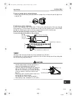
In case of bottom right or bottom left piping
• After scribing slits of the front panel with a knife or a marking-off pin, cut them with a pair of nippers or an
equivalent tool.
▼
Left-hand connection with piping
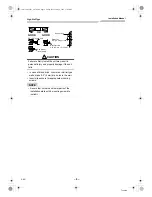
Bend the connecting pipe so that it is laid within 1.7” (43 mm) above the wall surface. If the connecting pipe
is laid exceeding 1.7” (43 mm) above the wall surface, the indoor unit may unstably be set on the wall. When
bending the connecting pipe, make sure to use a spring bender so as not to crush the pipe.
Bend the connection pipe within a radius of 1.2” (30 mm).
To connect the pipe after installation of the unit (figure)
NOTE
If the pipe is bent incorrectly, the indoor unit may unstably be set on the wall.
After passing the connecting pipe through the pipe hole, connect the connecting pipe to the auxiliary pipes
and wrap the facing tape around them.
CAUTION
• Carefully arrange pipes so that any pipe does not
stick out of the rear plate of the indoor unit.
• Carefully connect the auxiliary pipes and connecting
pipes to one another and cut off the insulating tape
wound on the connecting pipe to avoid double-taping
at the joint, moreover, seal the joint with the vinyl
tape, etc.
• Since dew results in a machine trouble, make sure to
insulate both the connecting pipes.
(Use polyethylene foam as insulating material.)
• When bending a pipe, carefully do it, not to crush it.
Slit
22.4” (570 mm)
Outward form of indoor unit
(To the fore front of flare)
R 1.2” (30 mm) (Use polish polyethylene core
or the like for bending pipe.)
Gas side
Liquid side
Use the handle of screwdriver, etc.
16.5” (420 mm)
1.
7”
(4
3
m
m
)
80
°
Indoor unit
Auxiliary pipes
Installation plate
12-EN
+001111052201_00Ta.book Page 12 Friday, November 20, 2009 11:45 AM
Summary of Contents for Carrier RAV-SP180KRT-UL
Page 86: ......
Page 87: ......
Page 88: ...1111052201 Toshiba 001111052201_00Ta book Page 87 Friday November 20 2009 11 45 AM ...


