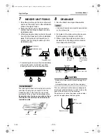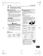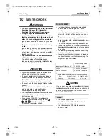
High-Wall Type
Installation Manual
– 18 –
Toshiba
EN
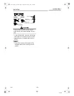
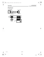
Wiring Connection
REQUIREMENT
• Be sure to connect the wires matching the
terminal numbers.
Incorrect connection causes a trouble.
• The low-voltage circuit is provided for the wired
remote controller.
(Do not connect the high-voltage circuit)
▼
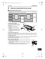
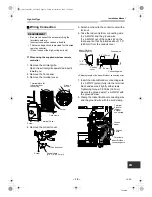
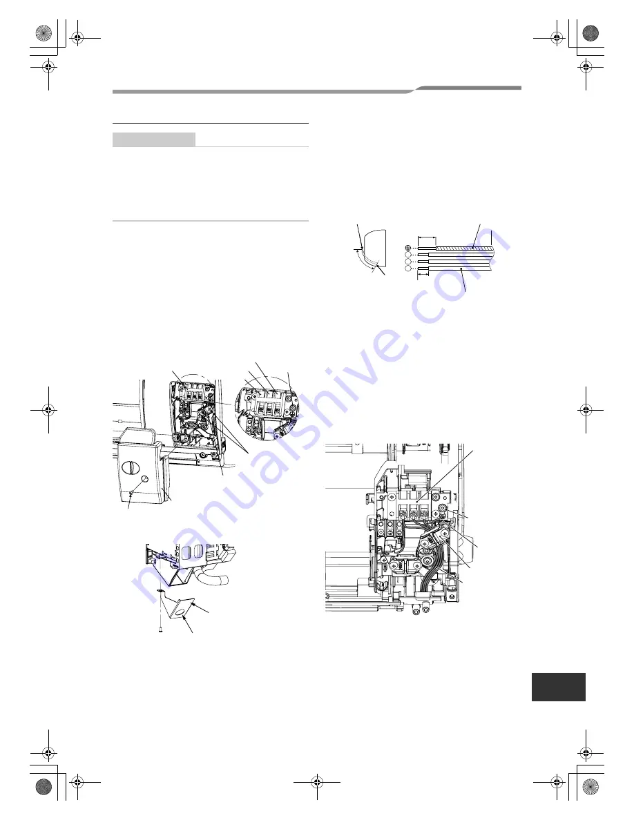
When using the supplied wireless remote
controller
1. Remove the air inlet grille.
Open the air inlet grille upward and pull it
toward you.
2. Remove the front panel.
3. Remove the terminal cover.
4. Remove the conduit cover.
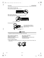
5. Attach a conduit to the conduit cover with a
lock nut.
6. Take the Indoor/Outdoor connecting wire
(3 x AWG12) and the ground wire
(1 x AWG12) out of the cable slot on the
rear panel so that it protrudes about 11.0”
(280 mm) from the conduit cover.
7. Insert the Indoor/Outdoor connecting wire
(3 x AWG12 (polar)) fully into the terminal
block and secure it tightly with screws.
Tightening torque: 0.9 ft•lbs (1.2 N•m)
Secure the ground wire (1 x AWG12) with
the ground screw.
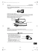
8. Clamp the Indoor/Outdoor connecting wire
and the ground wire with the cord clamp.
L
1
L
2
S
L
1
L
2
S
Terminal block for
indoor/outdoor
connecting
Screw
Cord clamp
Terminal Cover
Screw
Ground
screw
Conduit cover
Conduit hole
(dia. 7/8” (22.2 mm))
Screw
S
L
2
L
1
Indoor/Outdoor
connecting wire
Ground wire
0.4” (10 mm)
0.8” (20 mm)
<Stripping length of the Indoor/Outdoor connecting wire>
Conduit
cover
11.0”
(280 mm)
Connecting wire
L
1
L
2
S
Terminal
block for
indoor/
outdoor
connecting
Ground
screw
Ground
wire
Cord clamp
Indoor/Outdoor
connecting wire
18-EN
+001111052201_00Ta.book Page 18 Friday, November 20, 2009 11:45 AM
Summary of Contents for Carrier RAV-SP180KRT-UL
Page 86: ......
Page 87: ......
Page 88: ...1111052201 Toshiba 001111052201_00Ta book Page 87 Friday November 20 2009 11 45 AM ...


